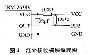
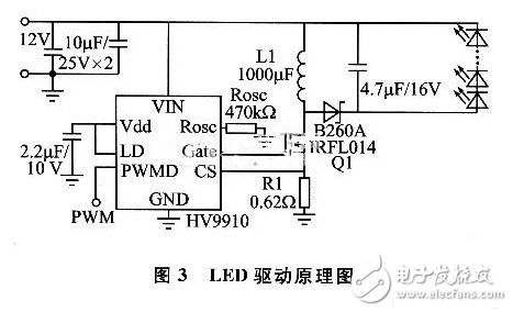
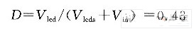
introduction LED lighting has entered the home user. Compared with traditional lighting equipment (such as incandescent lamps and fluorescent lamps), it has the advantages of high purity, color, efficiency, and light intensity. Aiming at the problem that the traditional illumination brightness is not easy to adjust and the switch position is fixed, this paper designs an LED remote control illumination system based on AVR single-chip microcomputer, and proposes the method of driving and brightness adjustment of LED illumination lamp. 1 LED lighting control system principle The system schematic is shown in Figure 1. When the infrared receiver receives the infrared remote control signal, the AVR MCU wakes up from the sleep mode through an external interrupt; the AVR MCU starts to parse the infrared signal, and if it matches the system address, it will change the LED constant current source drive according to the parsed command. Input to change the state of the LED light. 2 system hardware design 2.1 Controller The controller uses the AVR microcontroller ATmega8. ATmega8 is an AVR microcontroller introduced by Atmel in 2002 in a small pin package. ATmega8 integrates 8 KB programmable F1ash, 512-byte EEPROM and 1KB internal SRAM; 3 PWM channels for any PWM pulse width modulated output less than 16 bits, phase and frequency adjustable; 1 programmable serial USART interface supports synchronous, asynchronous and multi-machine communication automatic address recognition; 5 power saving modes. In this system, the main function of the controller ATmega8 is to analyze the infrared signal and control the LED driver. 2.2 Infrared receiving module The main components of the infrared receiving module use IRM-2368V, which is commonly used in home remote control of home DVD, TV, air conditioner and other appliances. IRM-2368V has the following characteristics: working voltage is 2.4 ~ 6 V; high sensitivity, strong anti-interference ability; can directly extract the remote control signal from the carrier, output matching TTL, CMOS level, can be directly interface with the microcontroller; The remote control distance can reach 12m. Figure 2 is a schematic diagram of the infrared receiving module. Among them, PD2 is multiplexed into ATmega8's external interrupt INTO, and the power supply part uses the system's 5 V power supply. 2.3 LED driver module The LED driver module uses the HV9910 integrated chip. It has the following characteristics: high energy efficiency over 90%; wide voltage input of 8 ~ 450 V; output current adjustable from a few mA to 1A; can drive up to 100 LED lights; PWM regulates current. Figure 3 is a schematic diagram of the LED constant current source driving, which is a typical buck-boost converter design. The input power supply voltage Vin=12V in the driver drives 3 to 6 3 50mA high-brightness LED lights. When the HV9910 is operating, the internal oscillation frequency fosc is determined by the resistance on the pin Rosc. In this design, Rosc takes 470 kΩ and sets the gate switching frequency of MOSFET Q1 to 50 kHz. R osc and fosc satisfy the following relationship (Rosc units are kΩ): Each LED lamp operates with a voltage drop of approximately 3 V. When three LED lamps are connected in series at the output, the driver output voltage is Vled = 91 V. The duty cycle D of the control signal of the Q1 tube when the LED is full current is available: Q1's on-time Ton=D/fosc=8.6μs, output current Iled=350 mA, and harmonic current suppression within 30%, the value of inductor L1 can be obtained from: In this scheme, L1 actually uses 1 mH. The feedback voltage on R1 is compared with the internal comparison voltage of 250 mV of HV9910. If the feedback voltage is greater than 250 mV, Q1 is turned off. R1 can be obtained from the harmonic current relationship:
Spindle For Insulator is a slender rod or pin used in insulators as a anchor point to connect the insulators with electrical wires or cables. The Insulator Spindle is an important part of the ceramic Pin Insulator Spindle, which determines the mechanical strength of the Insulator Long Shank Spindle. Its purpose is to fix the insulator on overhead transmission lines or substations, and can use strain clamps, U-bolts, plates and various accessories.
We warmly welcome friends both domestic and abroad to visit our company, if you have any questions, please contact with us directly.
Insulator Spindle Insulator Spindle,Spindle For Insulator,Pin Insulator Spindle,Insulator Long Shank Spindle FUZHOU SINGREE IMP.& EXP.CO.,LTD. , https://www.cninsulators.com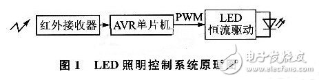


Advantage
1. No waste electric energy
2. Large grip strength
3. Easy to install
4. Make pressure balanced
5. Smooth surface long service life
6. Versatility


