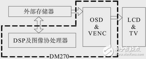
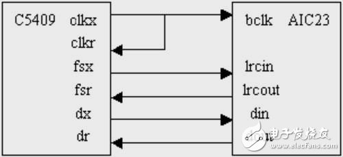
The 21st century is the digital age, and the demand for digital consumer products is growing at an alarming rate. Among these products, the proportion of video products is quite large, and it is becoming more and more popular in people's daily life. Among these products, whether it is a digital video camera or a mobile phone with camera function, the core part is the audio and video processor. What kind of processor is chosen determines the cost, performance and market prospect of such products. In this design, the author selected TI's TMS320DM270 (DM270) as the core processing chip. Feasibility Analysis In order to enable consumers to obtain higher quality digital video and video content, it is aimed at digital cameras, digital video cameras and portable multimedia products with a pixel count of 3 million to 5 million pixels. Texas Instruments (TI) introduced the DSP-based digital media processor DM270, which is based on a multi-processor architecture, integrated dual-core architecture of DSP C5409 and 32-bit RISC processor ARM7TDMI, which ARM7TDMI handles non-imaging functions, used as The main controller of the entire system, the DSP handles audio and video coding, and also integrates an image processing engine (iMX) dedicated to performing motion estimation and compensation in DCT, inverse DCT, and many other processing operations, as well as variable length coding. Decoder (VLCD). And TI also offers a range of audio and video chips that can be seamlessly connected to the DM270. The TVP5040, TVP5145 can be used as a video A/D converter, and the AIC23 can be used as an audio A/D. The DM270 also has a dedicated MMC/SD controller for external MMC/SD card expansion, which provides convenience for large-capacity data storage, as well as OSD (on screen display) module, which can directly connect external display devices (LCD, TV). . The basic system framework of the digital camera based on DM270 is shown in Figure 1. Figure 1 System diagram of the scheme Design As can be seen from Figure 1, the entire system front end is mainly composed of a video input module, an audio input module, and a processor DM270. The back end can access storage devices and display devices (LCD, TV). Video module The video input module structure is shown in Figure 3. The data is collected by the front-end CCD module. After entering the CPU, it is pre-processed, and then the video data is compressed and saved. Figure 3 video playback data stream Figure 4 Interface between McBSP and AIC23 Video capture and input The DM270 has a CCD programmable control interface that allows easy access to standard CCD (CMOS) data to the system and provides the necessary timing logic for CCD image sensors for progressive and interlaced CCD or CMOS images. The sensor is well supported and can support up to 4096*4096 pixels. In the system developed by the author, the OV7620 CMOS camera is used, and the YUV data is output directly into the system. There is also a hardware 3A module inside the chip to automatically adjust the focus of the lens. In addition, the DM270 has a preview engine that enhances the image of the CCD data, auto white balance and zooming in various sizes. This greatly reduces the CPU's primary processing pressure on the data. Video compression The DM270 supports MPEG4 30fps real-time codec at VGA resolution and supports multiple video compression standards such as JPEG, moTIon-JPEG, H.263 and more. A variety of shooting modes are available for digital video cameras. As mentioned earlier, the DM270 also has an image coprocessor iMX inside, which can perform DCT, motion estimation (compensation), and interpolation operations at high speed. The VLCD module completes the code stream encoding. In the platform developed by the author, it can achieve VGA MPEG4 24 frames per second, H.263 30 frames per second real-time compression encoding and decoding and display through LCD. In addition, in addition to video images, digital photo capture can also be implemented to capture JPEG images. A 2048*1536 JPEG image can be implemented in the platform developed by the author. Video output display The digital camera must have a cashback function, while the DM270 has an OSD controller with a VENC (video encode) and D/A conversion module at the back end to generate NTSC or PAL format video signals for output to external display devices. The DM270 will compress the MPGE4 data or JPEG pictures, and the decoded YUV data will realize the recall function through the OSD. Its data flow is shown in Figure 3. The OSD module has 4 image layers (two YUV video layers and two bitmap layers), which can easily realize layer stacking of layers. The OSD bit layer 0 can be used to display various operation menus as a graphical interface for the user to adjust system parameters.
The RGBW Color Controller is in a predetermined order to change the main circuit or control circuit wiring and circuit changes the resistance value to control the motor start, speed, braking and reverse master device to control RGBW color.
The same design with RGB Color Controller . The difference in coding for RGB and Rgbw Color Controller.
Specific comparison is as follows: a combination of hardwired logic controller, also known as the controller, by the logic circuit, relies entirely on hardware to achieve the function of the instruction.
RGBW Color Controller Basic components
Mingxue Optoelectronics Co.,Ltd. has apply the I S O 9 0 0 1: 2 0 0 8 international quality management system certificate, we apply the CE, RoHS and SAA certificate for our led lighting product.
Our R & D team can handle highly customized designs and offer OEM and ODM services.
RGBW Color Controller Rgbw Color Controller,Rgbw Rainbow Color Led Dmx Controller,Black Rgbw Color Controller,White Rgbw Color Controller Shenzhen Mingxue Optoelectronics CO.,Ltd , https://www.led-lamp-china.com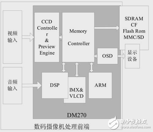

Cumbersome, complex structure, once the design is complete, you can not modify or expand, but it's fast. Micro-controller design program easy, simple structure, convenient to modify or expand, modify a machine instruction function, simply restated the corresponding micro-program;
To add a machine instruction, just add some micro-control program in memory, however, RGBW Color Controller is through the implementation of a micro program.

(1) the instruction register is used to store instruction being executed.
(2) Operation code decoder: instruction opcodes for decoding to produce the corresponding control level, to complete the analysis function of the instruction.
(3) Sequential Circuits: used to generate a time stamp signal.
We hope to set up a long-term partnership with you through our high quality products and our Sincere Service!

