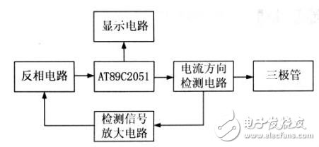
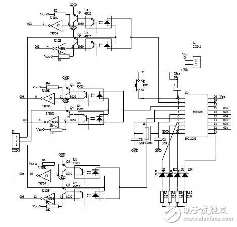
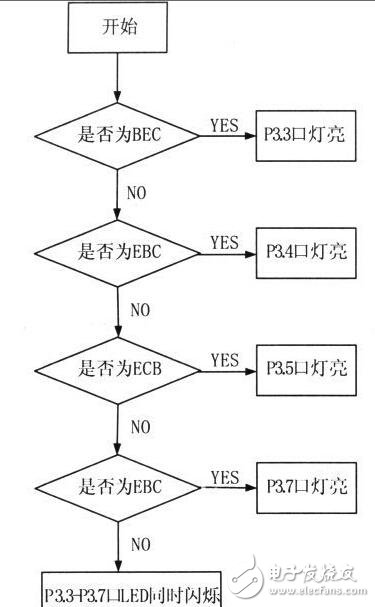
introduction In electronic technology, the triode is a very common component. The parameters of the three-stage tube are closely related to the measurement scheme and measurement results of many electrical parameters. Therefore, in the electronic design, the pins of the triode, The type of judgment and measurement is very important. There are many methods for measuring the triode pins. The commonly used ones in the laboratory are to measure the characteristics of the pins of the multimeter and the triode. However, due to the complicated relationship between the voltage and current between the pins of the triode, and the small size of the triode itself, The measurement brings great inconvenience, and there is currently no device for automatically determining the type and type of the triode tube. Therefore, it is especially important to design a circuit that automatically discriminates the triode pins and types. 1 hardware circuit composition principle According to the types of commonly used triodes and the arrangement of the pins, the automatic discriminating circuit designed includes four parts: a central control unit, a conversion circuit, a detection amplifying circuit and a display circuit, as shown in Fig. 1, in which AT89C2051 is used as a central control unit. Figure 1 System block diagram of the discriminator 2 hardware circuit design Figure 2 shows the schematic diagram of the automatic identification hardware circuit of the triode pin type. The hardware circuit mainly includes the single chip AT89C2051, the inverter CD4069, the photocoupler 4N25, 74LS06, 74LS07, several resistors and capacitors. Figure 2 Discriminating circuit schematic First, three binary codes (high and low levels) are sent from the P3.0~P3.2 ports of the MCU, and sent to pins 1, 2 and 3 of the triode. For different triodes, when the MCU sends different codes, the current directions on pins 1, 2 and 3 are different, there are two cases of inflow and outflow, and two optocouplers are used in reverse parallel to detect which direction. A current passes through, and the three-digit binary code becomes a six-digit binary code. The detected electrical signal from the optocoupler is amplified. Since the output signal is not the standard high and low level, it cannot be directly recognized by the single chip microcomputer, and the phase does not meet the requirements. Therefore, the first stage inverter CD4069 is used for inversion. Then, the standard six-digit binary code output from the inverter is sent to the P1.0~P1.5 port of the single chip microcomputer. The MCU compares the data read from the P1 port with the data written in advance by the MCU. When the corresponding conditions are met, the detection result is output from the P3.3~P3.7 port, and finally the LED is used to display the corresponding triode type. 3 software design Because the commonly used small and medium power triodes in the NPN triode pin arrangement order are EBC, ECB, BCE three (with a few exceptions, can be ignored), and PNP only EBC one sort order. Therefore, the software is written according to this rule. The overall programming idea is to apply different voltages to the three pins of the triodes of different pinout sequences, test their current conditions and convert them into binary codes. Write these binary codes into the MCU, and the external input data is compared with the binary code inside the MCU. If the read data is equal to a certain data written in advance, the measured triode is the corresponding triode of the data. The tube type and the pin are then illuminated with corresponding LEDs to indicate the tube type and the pin. The main program flow chart of the software is shown in Figure 3. Figure 3 program flow chart Single Phase Ac Motor,Ac Single Pole Motors,Single Phase Motor,Single Phase Motor Connection Changzhou Sherry International Trading Co., Ltd. , https://www.sherry-motor.com