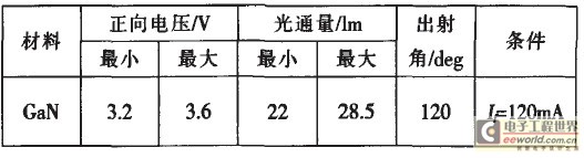
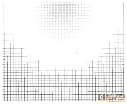
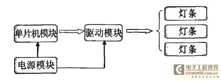
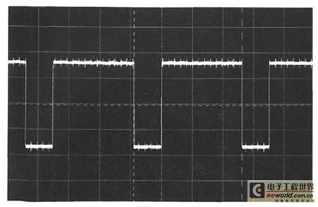
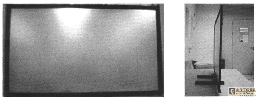
introduction The LCD screen itself does not emit light. In order to clearly see the contents of the LED display, a certain white backlight is required. The backlight is an optical component present inside the liquid crystal display, consisting of a light source and the necessary optical auxiliary components. The conventional backlight uses a cold cathode fluorescent lamp (CCFL), which has poor color reproduction and contains mercury vapor which is harmful to the human body. LED backlights have good color reproduction, long life, no mercury, and are good for environmental protection. As far as the driving circuit is concerned, the conventional CCFL backlight driving circuit is very complicated, and requires a driving voltage of several thousand volts, which can be driven by a special inverter. The LED can work at low voltage, the response speed is fast, and the control is convenient. In recent years, LED has been gradually introduced into the existing liquid crystal display technology, and the backlight is very likely to become the next industry monopolized by LED. LED backlights are far superior to CCFL backlights by adding contrast and area control. At present, LED backlights have been popularized in small and medium-sized panels, such as mobile phones and digital photo frames. With the development of LED technology and the continuous maturity of LED chips, LED LCD TVs may gradually replace traditional CCFL LCD TVs. The backlight is divided into a direct type backlight and an edge type backlight according to the position of the light source. The direct-type backlight directly places the LED light source under the light-emitting surface, and the light emitted by the light source is diffused and mixed by a space distance and a diffusion plate, and then becomes a surface light source, and the direct-type backlight needs a certain mixing distance. The edge-lit backlight structure is superior to the ultra-thin module design. With the “ultra-thin wind†blowing, large-size ultra-thin side-lit LED backlights have become the research of major TV manufacturers and upstream enterprises. Hot spot. 1 Structural design The LED backlight designed in this paper is an edge-light ultra-thin structure. The whole structure includes: LED light bar, driving board, film material, light guide plate, heat sink block, upper frame and back plate. The backlight uses white LEDs. The entire structure is designed with the center point of the Active Area as the design center for all components. The other dimensions are designed on the premise of the size of the LCD screen used in LCD TVs. The structure is designed considering the requirements of circuit design and optical design. The structural design begins with the UIVOUT layout diagram, expressing the overall mechanism and the assembly relationship between the components, and then proceeding with the part drawing structure design. The upper frame adopts a segmented design and is segmented in the length direction to avoid lengths that are too long. The outlet end of the light bar is placed at the four corners of the back plate to reduce the length of the winding. 2 optical design The function of the backlight module is to make the light emitted by the point source pass the diffuse reflection to make it a surface light source. In order to obtain a qualified surface light source, we must first select the appropriate LED. This design uses a white light two-chip LED. Through the preset white field photometric index, combined with the research and analysis of the influencing factors such as liquid crystal screen and optical film, the calculation of the luminous flux required for the entire backlight is completed. Based on the calculated luminous flux, the number of LEDs required is calculated in conjunction with the optical characteristics of the LED. Table 1 shows the electrical and optical characteristics of the selected LED. Table 1 LED electrical and optical characteristics In order to improve the brightness of the backlight, the structure of the film is: a diffusion sheet + a layer of BEF + a layer of DBEF. Among them, the role of the diffusion sheet is to atomize the light by the refraction and reflection of the diffusing substance, so that the emitted light is more uniform: the function of the BEF is to gather the light and make it vertically enter the liquid crystal module to improve the brightness: DBEF is utilized by the original Conventional absorbing polarizers absorb 50% of the light to increase brightness. The diameter of the light guide plate dot is 0.54~1.55mm. Figure 1 shows the partial dot distribution of the light guide plate. Figure 1 Light guide plate dot distribution map 3 circuit design LED backlight circuit design mainly includes the design of the light bar and the design of the drive control circuit. Figure 2 shows the block diagram of the whole circuit part. Figure 2 circuit structure block diagram 3.1 Light strip design The light source uses a two-chip white LED, and the light bar is distributed around the backlight. In order to achieve better current uniformity, the light bar is serially and mixed, and two or more strings are implemented. In order to achieve better heat dissipation, LED strips are fabricated using aluminum substrates. The entire system input voltage is 24V, which is provided by an external power converter. 3.2 Drive Control Circuit Design The driver chip is a three-way peak current mode PWM controller that provides high-precision LED current through closed-loop control of the output current. The chip contains three peak current mode controllers that provide feedback to the IC to ensure higher efficiency and higher accuracy. The on-chip gate drivers are optimized to drive 0.25A source current or O.5A sink current logic level FETs, each of which can be individually dimmed by linear or PWM dimming methods. The chip's closed-loop system dynamically adjusts its output voltage to accommodate line current and load regulation of the LED current. The three-in-one driver integrated in a single package ensures better current matching between each string while reducing the number of chips in the entire system. With a 40V linear regulator, 5V power supply is provided to lC, the switching frequency of the three converters is controlled by the internal oscillator, and the three channels have a phase difference of 1200 to reduce the input current ripple. High voltage drive, good current matching. The current accuracy of the LED string is 4-2%, supporting linear and PWM dimming. Figure 3 PW_M_ waveform (D = 75%) 3.3 Thermal design Due to the low light efficiency of the LED, a large amount of heat is generated during operation. If the heat dissipation problem is not solved, the brightness of the LED light is attenuated and the service life is shortened. In order to suppress the heat generated by the LED from affecting the brightness and chromaticity of the backlight module, it is necessary to heat-dissipate the LED. In order to achieve better heat dissipation, the LED array is soldered on an aluminum substrate (MCPCB), which has many times better heat dissipation than an ordinary PCB (FR4 material PCB). Under the aluminum substrate, a long heat sink is designed. Apply a heat-conductive double-sided tape between the heat-dissipating block and the light bar, and fix the aluminum substrate and the heat-dissipating block with screws. A heat transfer sheet with a protective film is applied to the heat accumulation zone around the backlight. In order to reduce the thermal resistance, a thermal via is added to the LED pad. In this way, the cross-sectional area of ​​the PCB board perpendicular to the heat flow direction is reduced, thereby reducing the thermal resistance between the top layer and the bottom layer and enhancing the heat conduction of the LED lamp. Finally, relying on the air convection in the TV case to dissipate the heat. 4 test results The ultra-thin LED backlight for LCD TVs designed in this paper is a side-light structure, and the light source uses white LEDs. Figure 4 shows the assembled LED backlight with a thickness of 9.9mm. A nine-point test was performed using BM-7, with a central luminance of 5,500 nit, brightness uniformity of 82%, and color reproduction of 95% @CIE 1976. The overall power of the backlight is 150W, of which the LED consumes 135W and the drive circuit efficiency is 90%. The driving circuit of the backlight system belongs to high voltage driving, the circuit is simple, and the current consistency is good. Figure 4 assembled backlight 5 Conclusion This paper designs an LED backlight for large-size ultra-thin LCD TVs with a center brightness of 5,500 nit, an overall backlight power of 150 W, and a brightness uniformity of 82%. The thickness of the whole machine is 9.9mm, reaching the leading level in the industry. The backlights designed in this paper have passed the reliability test, laying the foundation for mass production. Diameter 30mm SPI 3D Tube , it also called 3d light and 3D Led Light Tube, we have different length 0.5m 3D tube, 1m 3D tube, 1.5m 3D tube and 2m 3D tube, the SPI 3D Led Tube can use for led dancing light. SPI LED Tube Light is similar DMX 3D LED Tube , but the control ic is different.
Diameter 20mm SPI 3D Tube, it also called meteor lights and Led Video Light , we have different length 0.5meters 3D led tube, 1meter 3D led tube, 1.5meters 3D led tube and 2meters 3D led tube , the SPI 3D LED Tube can use for led dancing light. Spi Led Tube Light is similar DMX 3D LED Tube, but the control ic is different.
Photo show of SPI 3D Tube:
Spi 3D Led Tube Light,3D Led Dancing Light,3D Led Light Tube,Led Video Light Shenzhen Iseeled Technology Co., Ltd. , https://www.iseeledlight.com