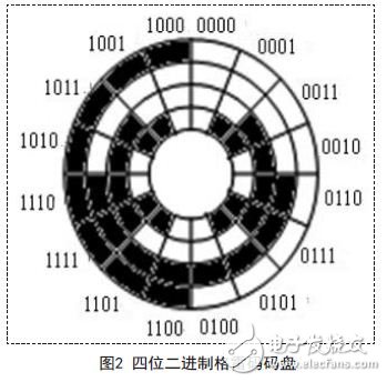
1 Introduction Photoelectric encoders are commonly used in modern motor control systems to detect the position and speed of a rotating shaft. They are high-precision angular position measuring sensors that convert mechanical geometric displacements on the output shaft into pulses or digital quantities by photoelectric conversion. Due to its high resolution, fast response and small size, it is widely used in motor control systems. 2. Optical fiber implementation of absolute value photoelectric encoder signal transmission The encoder is divided into an absolute encoder and an incremental encoder according to the signal output form. The absolute photoelectric encoder has the advantages of direct output interface with PLC module, ARM or FPGA, and has no cumulative error. However, the price is high and the manufacturing process is complicated, so it is not suitable for miniaturization. There are two types of absolute encoders, single and multiple. The single-turn absolute encoder automatically returns to zero after one rotation; the multi-turn absolute encoder rotates to the encoder's maximum number of turns, and the maximum count value automatically returns to zero. Absolute encoders are generally coded using Gray code discs. When GrayCode converts between any two adjacent numbers, only one digit changes. Take the resolution of 24 four-digit binary code disk as an example. If the absolute encoder uses a binary 8421 code disc, as shown in Figure 1, there is one or more bit positions between the two sequential codes. For example: two sequential binary codes, changing from 0111 to 1000, all bits of the binary code change their state. It may be wrong to get a reading at the transition moment of changing the state. That is, the synchronization and sampling of the position becomes very difficult. The binary Gray code disc is used, as shown in FIG. 2, between the two sequential codes, from the last bit code to the first bit code, only one bit position is changed, so that the position synchronization and sampling become accurate, Simple and feasible. For the conversion relationship between the natural binary code and the Gray code, reference can be made to the related literature. Absolute encoder signal output generally has parallel output, serial output, bus type output, and variable output integrated output. The following is a brief introduction to its output method. 2.1 parallel output Absolute encoder output is multi-digit digital (Gray code or pure binary code), parallel output is multi-point high and low output on the interface to represent digital 1 or 0, for the absolute encoder with low digits Generally, the digital output is directly outputted in this form, and the I/O interface of the PLC or the host computer can be directly input, and the output is instantaneous, and the connection is simple. But the parallel output has the following problems: 1 must be Gray code, because if it is a pure binary code, there may be multiple changes in the data refresh, the reading will cause wrong code in a short time. 2 All interfaces must be connected well, because if there is a bad connection point, the potential of this point is always 0, which causes the wrong code and cannot be judged. 3 transmission distance can not be far, usually one or two meters, for complex environments, it is best to have isolation. 4 For a large number of bits, many core cables are required, and it is necessary to ensure good connection, which brings engineering difficulties. Similarly, for the encoder, there are many node outputs at the same time, which increases the fault damage rate of the encoder. 2.2 Synchronous Serial (SSI) Output Serial output is a sequence of data output in time. The physical form of the connection is RS232, RS422 (TTL), RS485, etc. The SSI interface, such as the RS422 mode, is connected by two data lines and two clock lines, and the receiving device sends an interrupted clock pulse to the encoder, and the absolute position value is output to the receiving device by the encoder and the clock pulse. Triggered by the clock signal sent by the receiving device, the encoder begins to output a serial signal synchronized with the clock signal. The serial output cable is small and the transmission distance is long, which improves the reliability and protection of the encoder. Generally, high-order absolute encoders are serially output. 2.3 Fieldbus output (asynchronous serial) The fieldbus type encoder is a plurality of encoders each connected by a pair of signal lines. By setting an address and transmitting a signal by communication, the receiving device of the signal can read a plurality of encoder signals by only one interface. The bus type encoder signal follows the physical format of RS 4 8 5. At present, there are various communication protocols, each has its own advantages, and has not been unified. The commonly used communication protocols of the encoder are as follows: PROFIBUS-DP; CAN; DeviceNet. The bus type encoder can save the connection cable and the receiving device interface, and the transmission distance is long. In the case of centralized control of multiple encoders, the cost can be greatly saved.
An Optical Distribution Frame (ODF) is a frame used to provide cable interconnections between communication facilities, which can integrate fiber splicing, fiber termination, Fiber Optic Adapters & connectors and cable connections together in a single unit. It can also work as a protective device to protect fiber optic connections from damage. Optical Distribution Frame,Odf Unit,Fiber Splitter Box,Fiber Termination Box Chengdu Xinruixin Optical Communication Technology Co.,Ltd , https://www.xrxoptic.com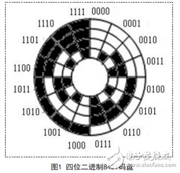
Rack mount ODF is usually modularity in design with firm structure. It can be installed on the rack with more flexibility according to the fiber optic cable counts and specifications. This kind of optical distribution system is more convenient and can provide more possibilities to the future variations. This ODF is 19", which ensures that they can be perfectly installed on to the commonly used standard transmission rack.