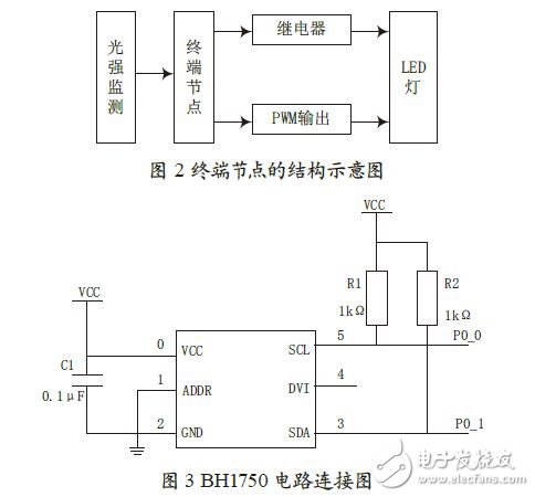
In order to improve the shortcomings of traditional indoor lighting system, such as complicated wiring, poor energy saving effect and difficult to control intelligently, the design and implementation method of indoor lighting system based on ZigBee technology is analyzed. The hardware design of the system is based on the CC2530 supporting the ZigBee SoC chip, and the software design uses TI's Z-Stack protocol. The system can realize single control, group control, full control and dimming control of the lamp node through the upper computer interface on the PC, and has the characteristics of low power consumption, low cost, no wiring and convenient installation. 0 Preface With the development of modern science and technology, people's pursuit of living standards is getting higher and higher. Smart homes have long been known to the public, and intelligent lighting systems, as one of the applications of smart homes, are getting more and more attention. The indoor lighting system mainly realizes various intelligent control and management functions for the lights inside and outside the house. Specifically, it mainly realizes single control, group control, full control, wireless remote control and multi-time timing control of the lamps. As one of the emerging short-range wireless communication technologies, ZigBee technology has the advantages of close range, low speed, low power consumption and high stability, which is very suitable for application in lighting systems. This paper presents an intelligent lighting system based on ZigBee technology. The system consists of several nodes in the form of an ad hoc network. Each node can adaptively adjust the brightness by sensing the change of external light intensity information, and can intelligently control each node through the control interface on the PC. control. 1 Introduction to ZigBee Technology ZigBee technology is a short-distance, low-complexity, low-power, low-rate, low-cost two-way wireless communication technology. It is a technical solution between wireless tag and Bluetooth. It has its own radio standard, IEEE 802.15. .4 (ZigBee) technical standard. This is a standard set by the IEEE Personal Area Network (PAN) Working Group. It is mainly used in applications where data throughput is small, network construction investment is small, security requirements are high, and power consumption is low. From the perspective of technical performance, ZigBee has the characteristics of low power consumption, short delay, short distance, high security, low speed, wide coverage, large network capacity, and low-cost market positioning, which is very suitable for lighting systems. The ZigBee technology network has three network topologies: star structure, tree structure, and mesh structure [5]. The star topology consists of a coordinator and multiple terminals, with no routing; the tree topology is a star network with a distance between the coordinator and the terminal, which needs to be routed; in the mesh topology, the coordinator, routing, and terminal Can communicate. In this system, a mesh structure is employed. 2 overall framework of the system The indoor intelligent lighting system consists of four parts: a coordinator, several terminal devices, multiple handheld wireless remote controls, and a PC host computer interface. The role of the coordinator in this system is to start and configure the network. The coordinator can maintain binding tables for indirect addressing, support associations, and design trust centers and perform other activities. A ZigBee network allows only one ZigBee coordinator with up to 65 536 end nodes. The coordinator acts as the sender of the command and the collector of the data in the system. The coordinator is connected to the PC through the serial port. After receiving the control command from the PC, it is sent to the designated node through its own ZigBee network. When the specified node receives the command from the coordinator, it makes the specified action and feeds it back to the coordinator. When the coordinator receives the data information from the terminal, it will be transmitted to the PC through the serial port. The wireless remote control can send control commands anywhere in the room to control one or more lights, making the entire lighting system more flexible. The coordinator mainly has CC2530+CC2591 module and serial port module. The terminal node mainly has CC2530+CC291 module, LED control module, temperature detection module and light intensity detection module. Figure 1 shows the overall framework of the system. 3 terminal control node design The hardware block diagram of the terminal node module is shown in Figure 2. It includes a light intensity detection module, a relay control module, and a PWM output module. The sensor used in the light intensity detection module is a photoresistor, and the new single-chip photometric chip BH1750 is selected, which better solves the drawbacks of the traditional photometric system. The BH1750 is a monolithic digital illuminance sensor developed by semiconductor manufacturer ROHM to meet the requirements of portable devices and liquid crystals, including mobile phone handsets, with excellent spectral sensitivity and 16 b serial output. Communication between the BH1750 and CC2530 uses the standard IIC communication protocol. The circuit connection diagram of BH1750 and CC2530 is shown in 3. Pins 3 and 5 of BH1750 are connected to P0_1 and P0_0 of CC2530 respectively, and R1 and R2 are pull-up resistors. The terminal control module includes a relay module and a PWM module. The relay module uses a triode to amplify the driving capability, and controls the opening and closing of the relay through the IO port output high and low level on the CC2530, thereby realizing the switching of the LED. The PWM module can control the brightness of the LEDs. The CC2530 can output an adjustable PWM wave with a frequency of 200 Hz and a duty cycle from 1% to 100%. The wireless remote control module is designed based on the terminal control node. It can automatically search for the ZigBee network and join the network to establish communication relationships, making itself a node, and then remote control the entire lighting system. The remote node module reads the value of the 4&TImes;4 keyboard from the PIC16F886 MCU, sends it to the CC2530+CC2591 module through the serial port, and then sends it to the coordinator, which sends the node to the node that needs to control the lamp.
Place of Origin:Dongguan, China (Mainland)
Gauge: AWG 28 to AWG 16
Length: Customized
A perfect replacement of the broken or old windshield washer nozzle
Car Wiper Blades,Obd Jumper Harness,Electrical Cable Gland,Auto Wiper Blade Dongguan YAC Electric Co,. LTD. , https://www.yacenter-cn.com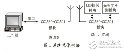
Connector: Molex, JST, TYCO, AMP, JAM, KET,Amphenol, Wago,Weidmuller, Phoenix,
Wires & Cables: UL, VDE standards
Inspection: 100% inspection before delivery
Certification UL, IATF16949, CE,
Design of indoor intelligent lighting system based on ZigBee
Application: Automobile Wire Harness
Features:
Superior plastic material. High quality and new brand
Working well with the washer wiper
Easy to install. Reliable craft
Durable. Not easy to be blocked by water