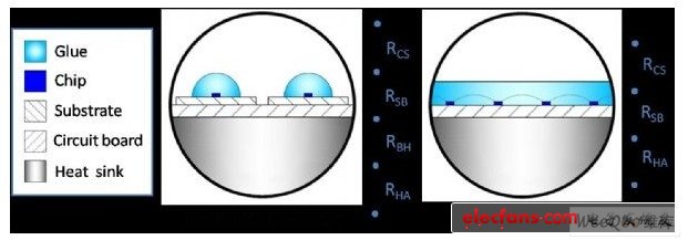
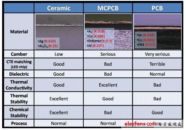
The traditional LED packaging process is to fix the LED chip on the heat dissipation substrate, connect the circuit through wire bonding or flip chip, and finally use glue and mold to form ( Molding) and other methods to wrap the LED chip to form LED die, and finally fix the die on the circuit board (Circuit Board), and integrate the power (Power), heat sink (Heat Sink), lens (Lens) and reflective cup (Reflector) constitutes a complete lighting module. Figure 1: Schematic diagram of LED package Table 1: Comparison of various circuit boards In the lighting module, the substrate and the circuit board are subjected to the most intense heat, so the substrate directly in contact with the heat source uses ceramic as a material, and when the power is getting higher and the components are getting smaller and smaller, the ceramic The circuit board is also gradually used in large quantities. As shown in Table 1, ceramic circuit boards have more advantages than traditional circuit boards for LED lighting. They can be applied to high-power (HP), high-voltage (HV), and alternating current (AC) LED lighting. These LEDs have The higher energy conversion rate or the advantage of not using a power converter, so integrating the two technologies can not only improve the stability of LED lighting, but also reduce the overall total cost, making it easier to introduce into the home lighting market. However, as the demand for greater illumination in a small size increases, the single crystal package no longer meets future requirements, so COB (Chip On Board) LED packaging technology has emerged, and it needs to be fixed on the substrate and integrated in the circuit with the traditional chip The package of the carrier board is different. As shown in Figure 1, the COB package is to directly encapsulate a single or multiple LED die on the circuit carrier board; in addition, it is known from the thermal ohm theorem ΔT = QR, temperature difference = heat flow x thermal resistance, The greater the thermal resistance, the greater the heat generated in the device, so the COB packaging method can eliminate the use of packaging substrates, reduce the number of lighting modules in series to enhance the LED heat dissipation performance. This technology can solve the high heat generated by a single high-power package, which has the advantages of low thermal resistance, low assembly cost and high lumen output of a single package. It has been widely used in lighting fixtures today, but due to the large number of chips The heat will directly contact the COB substrate. Therefore, when a higher illuminance lighting module is required, the COB made by the old aluminum PCB (MCPCB) technology will have a problem of thermal tilt due to mismatch in thermal expansion coefficient, so the introduction of ceramic substrate technology There is an imperative demand. Brushless Dc Driver,Brushless Dc Motor Driver,3 Phase Bldc Driver,Brushless Dc Servo Driver 3Kw Jinan Keya Electron Science And Technology Co., Ltd. , https://www.keyaservo.com