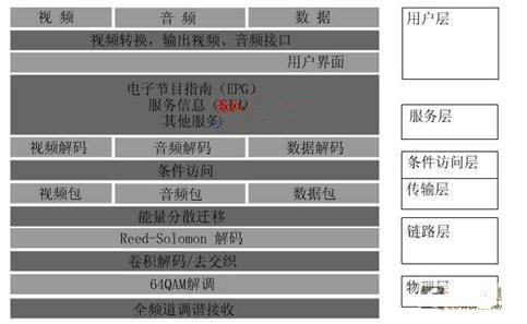
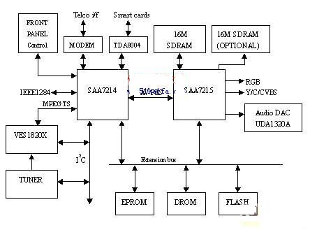
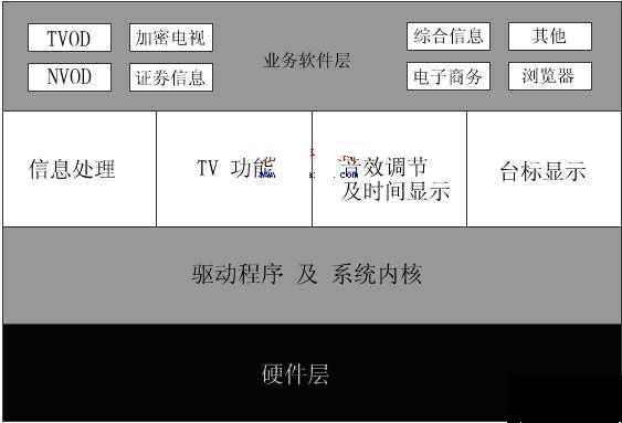
1 Introduction This article refers to the address: http:// The dissemination of information mainly includes three major network systems: communication network, radio and television network and computer network. With the rapid development of communication technology, television technology and computer technology, the three major networks have entered a new era of mutual integration. Interactive TV (ITV) is the embodiment of this combination. The so-called interactive TV is a video distribution service controlled by the audience. In the program and in the program, the viewer can make his own choices and decisions. It is a new type of television technology with asymmetric duplex communication mode. Among them, digital set-top box (STB) is one of the key technologies to realize interactive functions. Through the STB audience sitting in front of the TV in the home, you can achieve a variety of services such as video on demand (VOD), home shopping, home office, video games, etc., but also can receive high-definition digital TV programs sent by TV stations on ordinary TV sets. . 2 system function scheme The system function is based on PHILIPS' STB5660 solution (SAA7214+SAA7215+UAD1320A). It can provide functions including QAM signal reception, demodulation, video and audio processing, and user interface. The system adopts a highly open modular structure design. The system front end compresses the analog video and audio signals into digital signals through MPEG-2 video coding, and multiplexes the multiple digital signals through the multiplexer, and then performs QAM modulation transmission. As the user's downlink digital signal. The user uses the telephone DTMF or BPSK as the uplink, and the information selected by the user can be transmitted to the system service center (system front end) through the uplink channel. In this way, interactive video on demand (VOD), stock information and analysis, and timely transactions, distance education, and information transmission can be realized in a broadband network (both cable television networks). 3 system logic structure According to the basic functions of the STB, the STB can be divided into six layers according to the logical level, as shown in Figure 1. Physical layer: Full channel tuning reception and demodulation. The QAM modulated signal transmitted from the HFC network can be demodulated. Link layer: convolutional decoding/deinterleaving, REED SOLOMON decoding, energy dispersion migration. The QAM demodulated output signal is processed to generate a data stream conforming to the MPEG-2/DVB standard. Transport layer: demultiplexing and data unpacking. The generated data stream is separated into video packets, audio packets and data packets, and transmitted to the corresponding chip for processing. Conditional Access Layer: Controls the operation of the descrambling function. In the set-top box, there is a corresponding permission confirmation function, and when the set-top box receives the permission confirmation information, the digital television program is decoded for the user to watch. Service layer: video and audio decompression, EPG (Electronic Program Guide) generation and decoding of data. The received data stream is decoded, encoded, and encoded in video, audio, and graphics. Figure 1 system logic structure User layer: Contains display, conversion, remote control operations, etc. of the user interface. The demodulated, decoded, and encoded video and audio signals (ie, analog signals) are respectively output from respective ports of the set top box. At the same time, the remote control can be used to control and switch all basic functions. 4 system hardware structure scheme According to the STB5660 solution and the functional characteristics of the IC chip, the hardware structure of the system is proposed, as shown in Figure 2. 4.1 Front End Decoding Section The front end part receives the signal output by the cable television cable, and after tuning frequency conversion, QAM decoding, deinterleaving, decoding RS code, descrambling, etc., outputs the standard code stream before MPEG-2 demultiplexing, that is, the transport stream (TS stream) ). This part is mainly done by a piece of VES1820X chip. 4.2 Transport stream and video, audio decoding part The transport stream and video and audio decoding sections are performed by the SAA7214 and SAA7215 chips. Among them, SAA7214 is responsible for the MPEG-2 source decoding of the TS stream, and separates the video and audio data streams, as well as the control of the peripheral I/O devices associated with the decoding. The SAA7215 is responsible for decoding, encoding, and dividing the decoded data stream into audio signals and video signals. The SAA7215 also has a complete memory structure, using DRAM, SDRAM, FLASH, etc., through these memory chips, the software runs faster. 4.3 Backend decoding part Backend decoding is done by SAA7215 and UDA1320A. The video signal is output by the SAA7215. The audio signal is output by the UDA1320A. UDA1320A is a single-chip positive-phase stereo DAC with bit stream conversion technology. It has low power consumption and low voltage operation mode; system clock with three different frequencies of 256, 384 and 512; different can be selected by static pin control Frequency; supports sampling frequency from 16KHZ to 48KHZ; integrated digital filtering and normal phase DAC. 4.4 Network interface for interactive applications The interactive application hardware implementation is partially done by the SAA7214 and the responsive network interface. 4.4.1 Telephone network connection using ADSL technology Telephone network connection using ADSL technology: The set-top box connects the smart card interface and the ADSL Modem through the peripheral serial port, and the parallel port is used to transfer data between the set-top box and the PC. The ADSL Modem is directly connected to the ADSL office through a telephone line, and can provide high-speed data communication with a downlink rate of 8 Mbits and user control information with an uplink rate of 640 kbits. The set-top box has a faster rate than the direct Internet access through ADSL, enabling high-speed interactive services with the ATM/OP network. 4.4.2 Hybrid network connection using fiber/coaxial cable technology (HFC) Hybrid network connection using fiber/coaxial cable technology (HFC): HFC downlink uses a digital tuner demodulator to convert the signal of the user selected channel into a baseband data stream; the upstream uses a modulator to send the user's control signal to the channel. The interface also uses a cable modem. 5 system software solution The software structure of the set-top box system can be divided into three levels: business software application layer, real-time event processing layer, system kernel and driver layer. The system software structure is shown in Figure 3. 5.1 Business Software Application Layer The business software application layer is a layer of interface that covers the driver and the operating system. It is developed according to the system business needs, and implements various functions of the set-top box for the user application. Such as comprehensive information, e-commerce, video games, etc. 5.2 Real-time event processing layer The real-time event processing layer is a software environment that isolates the application from the low-level operating system and hardware details. It makes the application independent of the specific hardware platform and is the middleware of the business software application and the hardware platform. OpenTV middleware is used. OpenTV middleware provides the user with a complete application interface for the application, allowing the application to implement all the functions of the set-top box system simply by calling these functions. This makes the work of the user application part very simple. 5.3 system kernel and driver layer The operating system used in this system is pSOS, and the hardware driver layer is mainly for various hardware modules and provides corresponding drivers. The main drivers include: interface modules, including I2C interface operation control, smart card control, etc.; audio module; video module; demultiplexing module; decoding module, Flash driver module. 6 Conclusion The above describes the logical structure, system functions and system hardware and software composition and implementation of the interactive digital TV set-top box based on the STB5660 solution. At present, the domestic broadcast television system has begun to change to digital TV. Although the digital application in the near future is more digital, the color TV is digitalized, but with the increase of user demand for functions and the richness of cable operators' services, Functional interactive digital TV set-top boxes are also becoming more widely used. Dual USB Charger,Round USB Charger,USB Charger Outlet,Round USB Charging Dongguan baiyou electronic co.,ltd , https://www.dgbaiyou.com