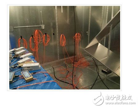
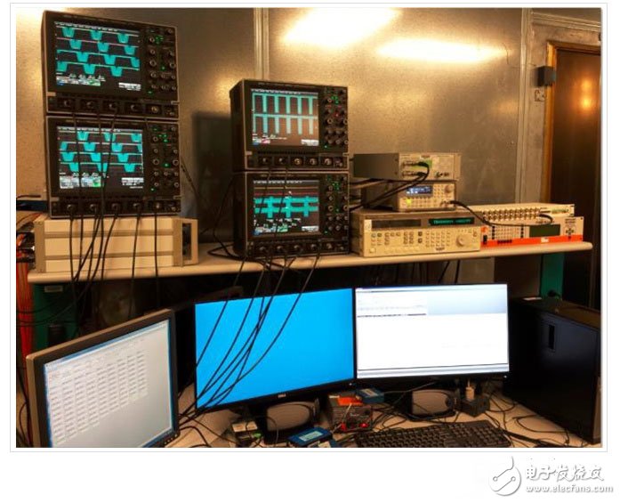
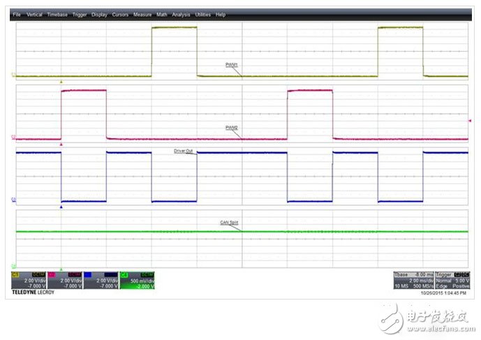
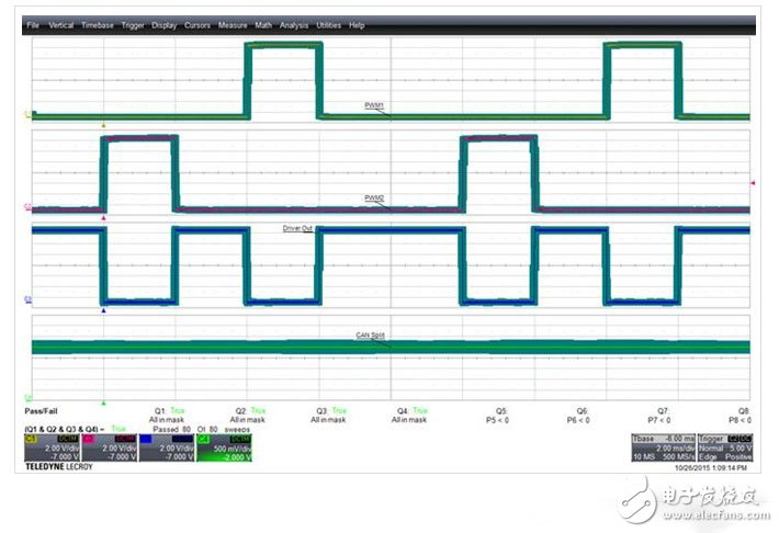
introduction Mobile phones, Bluetooth headsets, satellite radio, AM/FM radio, wireless Internet, radar, and other countless potential electromagnetic interference sources emit electromagnetic waves mixed in the real world, in order to ensure that the electronic components in the car are still robust and effective They require EMI interference testing in a controlled environment. The radiated immunity chamber is a completely sealed conductive space and is an ideal EMI test environment because it fully controls the frequency, direction, and wavelength of the electromagnetic field generated in the space. And because the electromagnetic field cannot enter the confined space, the automotive components tested in the immunity chamber can receive accurate and highly controllable electromagnetic waves during the test. At the same time, electromagnetic waves cannot leave the interference room, and the measuring instruments used for testing and the engineers operating outside the disturbance-proofing area can be protected from the strong electromagnetic waves generated in the interference room. Modern cars contain hundreds of electronic circuits to achieve a wide range of functions related to safety, entertainment and comfort. These automotive electronic components, also known as electronic control units (ECUs), must meet stringent EMI interference standards. Electromagnetic interference room configuration Inside the EMI room, typical device-level immunity test setups include the electronic control unit (ECU) being tested, the wiring harness, and an emulator containing the actual or equivalent electronic load, as well as a series of peripherals to represent the automotive electronic control. The interface of the unit (ECU); the transmitting and receiving antennas are used to generate electromagnetic waves of high field strength; and the mode tuner is placed in the interference chamber to change the geometry of the space to create the electromagnetic field effects required for the test. The automotive electronic control unit (ECU) operates in a preset mode and is exposed to the electromagnetic interference field. In the process of exposure to the source of interference, it is verified by monitoring the response of the electronic control unit (ECU) of the vehicle whether it exceeds the allowable tolerance. For most RF interference tests, the deviation detection from the plan needs to determine the device anti-interference threshold, which is determined by gradually adjusting the amplitude of the interference source until the function of the electronic control unit (ECU) of the vehicle deviates. The automotive electronic control unit (ECU) under test needs to meet strict ISO (Standardization International Organization) rules, as well as the requirements between automotive manufacturers and automotive electronic control unit (ECU) component suppliers. Because each electronic component has a slight difference in immunity to electromagnetic fields, performance deviations between detection and acceptable standards, and when these values ​​exceed the test plan rules, it is the task and responsibility of the EMI test engineer. The method of determining whether the automotive electronic control unit (ECU) is still working properly during the EMI test is to let it output its working state through the output port of the ECU such as the CAN bus. Other ECU outputs also include analog sensor outputs and pulse width modulated outputs that drive the actuator. Field strength and consideration A typical example of the field strength and frequency type used in the radiated RF immunity test described in ISO/IEC 61000-4-21 uses a reverberation chamber containing a mechanical mode tuner when in a given test. When enough tuner positions are obtained at the frequency, the reverberation chamber free space produces a uniform test frequency range of 0.4 to 3 GHz, field strengths up to 200 V/m (CM and AM), and 600 V/m (radar pulses). field. In another example, the conducted RF immunity test described in ISO 11452-4 uses a clamp current injection probe to induce RF current into the DUT harness, with a frequency range of 1-400 MHz and a range of tens to several. One hundred mA, so that a strong enough field can be created near the test platform to affect the operation of unshielded equipment. Such a test environment avoids the direct connection of the test instrument to the test setup. One of the challenges is that the output data of the automotive electronic control unit (ECU) comes from an enclosed space that is isolated from the test area, and the test instruments and testers are outside the enclosed space, so there must be a way to create the enclosed space. The data is transferred outside the closed space for analysis. Since conventional cables such as BNC or SMA cables are themselves electrically conductive and susceptible to electromagnetic waves from inside the interference chamber, the optical transmitting and receiving unit and the optical fiber need to be used to interfere with signals from the ECU inside the room. Transfer to the test equipment located outside the interference room. The fiber is a non-conductor so it is not affected by the electromagnetic field in the room. In order to connect the cable from the interior of the interference chamber to the test equipment, the waveguide is used to output an optical signal at the boundary of the interference chamber, thereby allowing the interference chamber to remain completely closed while outputting the signal from the ECU. The fiber waveguide has a high-pass cutoff frequency that is higher than the frequency range tested in the interference chamber and therefore does not interfere with the environment created in the interference chamber. Electromagnetic interference test equipment settings Figure 1 below is a picture taken in the space of the closed interference room (when the transmitting antenna is off) for the actual setting of the offset detection in the anti-interference test. The mode tuner is located on the right side of the interference chamber. There is a CAN bus fiber transmitter on the left side of the interference chamber, which is placed on the foam platform. The relative dielectric constant of the platform is 1.4 and is located in the available space of the reverberation chamber. The fiber optic transmitter converts the ECU's output signal into light and then enters the fiber from RF interference and exits the reverberation chamber from the near-floor position through the waveguide. The ECU used for testing, as well as the transmitting and receiving antennas, are also located inside the reverberation chamber and are not shown in this figure. Figure 1 Reverberation chamber with mode tuner (right) and fiber transmitter (left). The antenna and ECU are not shown in the figure, but they are also present. A typical test method is that signals arriving outside the reverberation are collected by the data acquisition device and require user-defined software to determine if the CAN bus signal, sensor signal, or PWM output output from the ECU meets specific needs. Because there are many signals to test and there are many test standards, the software development time and cost of describing all the test requirements in the test plan will be very long and expensive. The use of oscilloscopes in EMI testing is a relatively unexplored approach to placing an array of oscilloscopes outside the interference chamber and using multiple oscilloscopes for real-time analysis. Because oscilloscopes already come standard with stencil testing and parametric threshold testing capabilities, many test requirements can be performed directly at once without the need for significant software development time. In Figure 2, the copper-colored door to the outside of the EMC interference chamber is located on the right side of the test platform. On the left side, the optical signal in the orange fiber carrying the functional test result is converted into an electrical signal and then input to the oscilloscope channel through the BNC cable. Figure 2 Oscilloscope array for dynamic analysis of anti-jamming data outside EMC interference Waveform templates in oscilloscopes are used to analyze waveform shapes relative to predefined consistency requirements. The size of the template depends on the functional criteria of the signal being measured and can be automatically adjusted during the test by the computer. In Figures 3, 4, and 5 below, an oscilloscope is being used to monitor the output of the simulated ECU. Using simulation data for confidentiality reasons, it is very close to observing the output of a typical ECU. Channel 1 and Channel 2 show the simulated PWM signal used to control an output drive actuator signal. The simulated actuator signal is captured on channel 3 and the CAN separation signal is captured on channel 4. Electromagnetic compatibility conformance test Figure 3 below shows the data signals collected by the oscilloscope after the template is turned off. The waveform shape of each signal can be clearly displayed and observed. The oscilloscope is based on the edge trigger of channel 2, and all four waveforms are simultaneously captured. Figure 3 The simulated ECU output signal includes the PWM signals for channels 1 and 2, the actuator output signal for channel 3, and the CAN separation signal for channel 4. In Figure 4 below, the template test is opened. The shape of the template can be used to verify signal high level, signal low level, frequency, duty cycle, and other specifications described in the test plan. The thickness of the template shows the specified tolerance band near the nominal value. Moreover, the template verifies whether each of the acquired waveforms deviates from the defined nominal value or a percentage that deviates from the nominal value. In this example, each waveform meets all test criteria. Of particular importance is the ability of the oscilloscope to continuously perform edge triggering using pre-defined template criteria for continuous monitoring of errors. The standard for oscilloscope triggering is that it appears on one edge of Channel 2, and the oscilloscope can be set up to identify and archive every error that occurs. Figure 4 Simulated ECU output signal, PWM signals displayed on channels 1 and 2, actuator drive output signal displayed on channel 3, CAN separation signal displayed on channel 4 are all within the defined tolerance template, passed the template test standard In Figure 5, the simulated ECU is affected by EMI in the interfering chamber, resulting in amplitude modulation, reduced amplitude, and changes in duty cycle and frequency such that the template test of the PWM signal and the actuator drive output signal fails. Unlike the other three signals, the CAN split signal is not affected by EMI and continues to pass the test. This type of template test method allows multiple standard quick tests to be performed simultaneously. Figure 5 After the EMI is applied, the simulated ECU output PWM signal and the actuator drive output signal cannot pass the template test, and the oscilloscope will prompt the operator to have an error. In addition to the waveform mask test, the Pass/Fail qualification test also applies to parameters that can be used to ensure that the measured value results meet specific specified values. As shown in the screen graph in Figure 5, the oscilloscope uses the red "Fail" information below the test criteria to indicate three failures. When a template test or parameter-qualified test failure event occurs, the oscilloscope can also perform some actions automatically, such as saving waveform data for direct comparison and archiving, saving screen images for archiving and evaluation, and generating a pulse signal for assisting automated testing. And issue a warning to inform the test operator that something is wrong. in conclusion Although in the anti-interference test, the oscilloscope can quickly perform the parameter measurement for determining the EMC deviation, the oscilloscope is often overlooked in the anti-interference test due to the lack of attention and sufficient number of oscilloscope channels in the past. Typically, the analysis of parameter results requires the development of user-defined software, and it is likely that the user will need to design the hardware themselves - both of which are time consuming and expensive. However, multiple oscilloscopes with pass/fail templates and parameter limit test capabilities can be combined directly to analyze the sensor output of each component. In anti-jamming tests, the oscilloscope array is the most cost-effective way to verify that the sensor output meets the requirements, as most of the functions can be done using the pass/fail template and parameter limit test functions already available in the oscilloscope. By spending the cost of developing your own data acquisition software to perform the same rigorous EMI deviation test, EMC engineers can save a lot of time and effort. 8Dn9 Gas Insulated Metal Enclosed Switchgear Square D Switchgear,Switchgear For Generator,Metal Switchgear,Siemens Switchgear Products Shandong Shunkai electrical equipment co., LTD. , https://www.chinasdsk.com