About Silicone Cake Molds:
In our kitchen,we usually use metal utensils,but sometimes,they will rust,and will be harmful our health.Is there anything that can take place of our kitchen utensils?
silicone cake mold is not only light,but also easy to carry,wherever you go,you can take it outside or other places.In a word,it's suitable for all people.
Other Type Silicone Cake Decorating Mold can be clicked on Silicone Cake Mould , Silicone Cake Tools ,Cake Decorating Silicone Molds.
10.Silicone Baking Molds photos for reference.
Silicone Cake Molds Silicone Cake Molds,Cake Silicone Mold,Cake Mold Silicone,Silicone Cake Decorating Mold,Silicone Cake Mould, Silicone Cake Tools,Cake Decorating Silicone Molds OK Silicone Gift Co., Ltd. , https://www.oemsiliconegift.com
First, high voltage LED
"High-voltage LED", one is the LED manufacturer to provide a series of small power LEDs, as shown in the left figure of Figure 1, it is only one type of integrated LED, and the main difference between the integrated LED shown on the right and the former is that The former is all in series, the latter is in series and parallel. The integrated LED is characterized by a slotting method on a large wafer, which is cut into a number of small LEDs, and then the trenches are filled with an insulating layer, and the wires connecting the LEDs are laid in accordance with the series and parallel requirements. 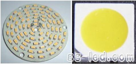
Figure 1 High voltage LED
Regardless of the "high-voltage LED", the linear high-voltage LED driver scheme discussed in this article is a smaller current (theoretical less than 100mA), higher voltage LED driver scheme.
The load characteristics of the LED are shown in Figure 2. According to the load characteristics of the LED, a controlled constant current source is required for control. After rectifying the power frequency AC voltage, if this voltage is directly applied to the output LED, the problem is that constant current cannot be achieved, and the LED current is not constant throughout the power frequency cycle, and the brightness can not be controlled. Life expectancy is greatly reduced. For high-frequency switching power supplies, CC (constant current) control is a common method. However, while the performance is improved, the cost is greatly increased. 
Figure 2 LED load characteristics
In the LED lamp bead load, an active or passive device is connected in series to make the line produce a "constant current-transformation" effect, so that the LED load passes through a constant current, and the external line is subjected to a varying voltage. This is how LDOs (Low Dropout Regulator) work. The driving method for realizing constant current and its development trend are described in detail below.
Compared with high frequency switching power supplies, the advantages of linear high voltage solutions are:
1. It saves the input electrolytic capacitor and output capacitor, which is a circuit with no electrolytic capacitor. The life of the electrolytic capacitor is the bottleneck of the power supply life, and the electrolytic capacitor is omitted, and the life of the driving power source is prolonged. Second, the circuit works in the power frequency linear mode, not working in the high frequency mode, eliminating the high frequency inductance, and there is no problem of EMI, eliminating the EMC circuit. Third, the elimination of high-frequency inductors and other peripheral components, further reducing costs.
Second and fourth generation HV LED driving method
The linear high-voltage LED driver solution has evolved to today and has gone through four generations.
2.1 First generation resistance capacity control method
The working principle of RC is to limit the maximum operating current by the capacitive reactance generated by the capacitor at a certain AC signal frequency. The capacitor buck is actually using the capacitive reactance current limit, and the capacitor actually acts as a limiting current and dynamic distribution. The role of the voltage across the capacitor and load. As shown in Fig. 3, since the on-resistance of the rectifier tube is only a few ohms, the dynamic resistance of the Zener diode VS is about 10 ohms, the current limiting resistor R1 and the load resistor RL are generally 100 to 200, and the filter capacitor is generally 100 uF~ 1000uF, its capacitive reactance is very small and can be ignored. If R is used to represent the equivalent resistance of all components except C1, the AC equivalent circuit of Figure 3 below can be drawn. At the same time, the condition of XC1>R is satisfied, so the voltage vector can be drawn. Since R is much smaller than XC1, the voltage drop VR on R is much smaller than the voltage drop on C1, so VC1 is approximately equal to the power supply voltage V, that is, VC1=V. According to the electrician principle, the capacitive reactance of the series capacitor is 1/2Ï€fC, and the 1uF and 50Hz AC power is taken as an example. The capacitive reactance XC=3185 ohms, the average DC current Id after rectification, and the average value of the alternating current I are Id= V/Zc.
Unfinished
For more information, please refer to the October issue of "High-tech LED-Technology and Applications" ![]()
Product introduction:
1.Product name:Cake Silicone Mold ,Cake Mold Silicone,Silicone Cake Decorating Mold,Silicone Cake Mould, Silicone Cake Tools,Cake Decorating Silicone Molds
2.Place of origin:Guangdong China
3.Color:any pantone color
4.Logo:Printing,debossed,embossed
5.MOQ:500pcs.
6.Package:1 pcs/opp,customized design is available.
7.Design:Customized/stock
8.Certification:FDA,LFGB,SGS,ROHS,etc.
9.Usage:Use in kitchen baking

Four generation linear high voltage LED driving scheme and its development trend
[Source: "High-tech LED - Technology and Applications" October issue Li Mingfeng / Zhang Zhansong]