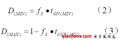
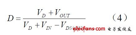
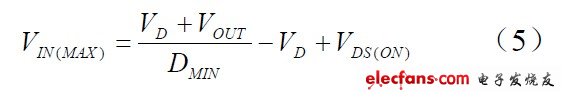
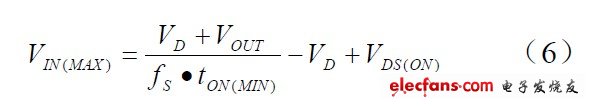
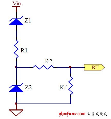
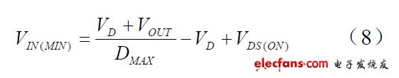
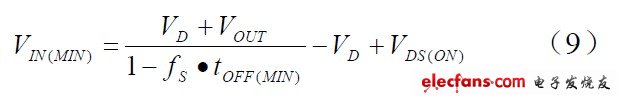
At present, high-frequency and high-efficiency DC-DC converters are increasingly used in automotive electronic systems. High switching frequency can use smaller power inductors and output filter capacitors, thereby reducing the size of the system as a whole, improving the compactness of the system, and reducing the cost of the system; high working efficiency can improve the use of car batteries Time, reduce the power loss of the system, thereby reducing the calorific value of the system, optimizing the thermal design of the system, and further improving the reliability of the system. However, a high switching frequency will reduce the operating efficiency of the system, so some compromises must be made between the switching frequency and the operating efficiency during design. This article mainly discusses some design skills and precautions including the above-mentioned problems when the DC-DC step-down BUCK converter is used in automotive electronic systems, and these problems are often details that are easily overlooked in engineering design. 1 Actual minimum and maximum input operating voltage 1.1 Switching frequency The switching frequency must be compromised between efficiency, component size, minimum input and output voltage difference, and maximum input voltage. High switching frequency can reduce the value of inductance and capacitance, so you can use smaller size and size of inductance and capacitance, and reduce costs. However, high switching frequency will reduce efficiency and reduce the actual maximum operating input voltage, as well as require higher input and output voltage difference. The highest switching frequency can be calculated by the following formula: Among them: f S (MAX) is the maximum switching frequency, tON (MIN) is the minimum on-time required by the switch, VD is the forward voltage drop of the freewheeling diode, VOUT is the output voltage, and VIN is the input for normal operation Voltage, VDS (ON) is the conduction voltage drop of the switch. The above formula shows: When t ON (MIN) is fixed, a low duty cycle requires a lower switching frequency to ensure safe operation of the system. Similarly, the low switching frequency allows a lower input and output voltage difference. The main reason why the input voltage depends on the switching frequency is that the PWM controller has a minimum turn-on t ON (MIN) and a minimum turn-off time t OFF (MIN). If its value is 150ns, that is to say, the on-time of the switch tube must last at least 150ns, below 150ns may cause the MOSFET to be unable to turn on normally; Similarly, the switch-off time of the switch tube should be at least 150ns, Below 150ns may cause the MOSFET to fail to turn off normally. This means that the minimum duty cycle and the maximum duty cycle are: The above formula shows that when the switching frequency decreases, the range of the duty cycle increases. The optimized switching frequency must ensure that the system has a sufficient input operating voltage range, while making the inductance and capacitance as small as possible. 1.2 Actual maximum input operating voltage Usually the input voltage of the chip has a certain rated working voltage range. In addition to the limitation of the rated working voltage, the actual input working voltage is subject to other conditions. The minimum actual input operating voltage is usually determined by the maximum duty cycle. The duty cycle of the BUCK converter is: At the highest input voltage, the duty cycle is the smallest. The maximum actual input operating voltage is determined by the minimum duty cycle of the PWM controller: If the output is under starting or short-circuit operating conditions, the input voltage must be lower than the following calculation results: It can be seen that the low switching frequency can be safely operated at a higher input voltage. The minimum on-time t ON (MIN) is the minimum duration that each controller can turn on the high-side MOSFET. It is determined by the internal timing delay and the amount of gate charge required to turn on the high-side MOSFET. Low duty cycle applications can approach this minimum on-time limit, and care should be taken to ensure: If the output voltage is in a regulated state, the system is not in a starting or short-circuit condition. If the input voltage is greater than the actual maximum allowable input operating voltage, the system can still work regardless of the operating frequency. In this situation, the duty cycle drops below the level that the minimum on-time can be adjusted, and the controller will start to enter the pulse skipping mode, that is, some pulses will be skipped to maintain the output voltage regulation. At this time, the output voltage The sum current ripple is larger than the output voltage and current ripple during normal operation. In general, when the peak detection voltage drops, the minimum on-time of each controller will gradually increase. For example, under light load conditions, the minimum on-time will gradually increase. In forced continuous operation applications with low ripple current, this This is particularly important. In this case, the duty cycle drops below the minimum on-time limit, and obvious pulse skipping occurs, and the ripple of current and voltage increases significantly. In addition, the saturation current of the inductor is usually more than 1.3 times the output current. For some severe working conditions such as starting and output short circuit and high input voltage, the saturation current of the inductor must take a larger value to ensure the safe operation of the system. Usually the switching frequency is fixed, but some synchronous buck controllers that use external resistors to set the switching frequency can add a voltage regulator Z1 and current limiting current R1 to reduce the switching frequency when the input voltage increases, thereby expanding the input voltage range, such as Figure 1. Figure 1: Frequency-reduction operating circuit at high input voltage The problem with this circuit is that at high input voltages, the output current and voltage ripple increase because the frequency decreases and the inductance is constant. The frequency changes in a wide range, the inductance cannot be optimized, and the loop compensation cannot be optimized. The minimum operating frequency of the system is set by increasing the voltage regulator Z2 and the current limiting current R2, thereby limiting the range of frequency changes. 1.3 The actual minimum input operating voltage When the input voltage is the lowest, the duty cycle is the largest. With a synchronous buck controller, the minimum actual input operating voltage is determined by the maximum duty cycle of the PWM controller: The relationship between the minimum operating voltage and the minimum off time t OFF (MIN) is: It can be seen from the above formula: when t OFF (MIN) is constant, a high switching frequency will increase the actual minimum input operating voltage. For a lower input operating voltage, a lower switching frequency can be used. In some synchronous buck controllers, when the pressure difference between the input and output drops to a certain value, the system will enter a full conduction or LDO control mode with a duty cycle of 100%. Barbecue machine is a barbecue food machinery and equipment, its main function is to do all kinds of barbecue products. Mainly used for barbecue shops, mobile barbecue and so on. Electric BBQ Grill,Smokeless BBQ Grill,Electric Chicken Grill,Vertical Electric BBQ Grill Ningbo APG Machine(appliance)Co.,Ltd , http://www.apgelectrical.com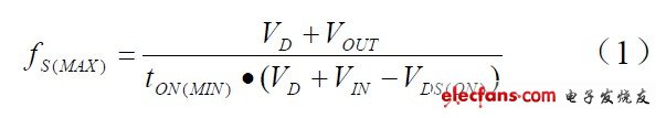

The use of rotary grill grill grilled after a piece of barbecue from the barbecue, accompanied by salad dishes, ingredients into a special made in the bread. Visibility, on-site production, and popular in Europe and the United States. Become one of the mainstream street food fast food.
1 power: the range of 800-1600W, according to the actual situation. 2 grilled food: steak, shrimp, vegetables, ham and so on. 3 functions: 3.1 baking pan with a raised stripes, relying on the protruding stripes to bake the food, there will be drainage structure, slope or drain hole. 3.2 baking time is about 3-5 minutes. 3.3 thermostat is adjustable, according to the different food or personal taste to adjust the different. 3.4 heat pipe: According to the different grades of products, choose different specifications of the heating pipe. Generally fixed in the back of the heating plate, using high temperature stainless steel tube or nickel-chromium alloy tube INCO840, the latter cost higher. 3.5 generally do not need PCB control, FireWire to increase the temperature insurance. 3.6 within the wiring: the general use of hidden lines, hidden in the activities of the hinge of the shaft. 3.7 Other: need to take oil device, a separate configuration or drawer type oil box. 3.8 turn on the power, the red power light, the machine warm, until the green light into the food, wait 3 to 5 minutes.