Figure 1: Common LCD TV system architecture Figure 2: Block diagram of the LCD panel controller ZhenHuan's junction box led drivers is the most compact metal case LED driver on the market with UL/CUL 8750 listed. The series led driver is class 2 rated and designed to provide Aluminum material housing and Iron material Housing for outdoor and indoor use. Encased in a low profile coated metal case with junction box, to enable easy installation that complies with electrical code requirements. China 12v Led Transformer,Dimmer Driver,Led Strip Enclosures Drivers,Ac Led Transformers,Low Voltage Transformer Outdoor,Led Driver Junction Box Shenzhenshi Zhenhuan Electronic Co Ltd , https://www.szzhpower.com
1. The need to use multiple frequencies in high-definition television systems-different standards and interfaces
Figure 1 shows the basic principle diagram of an LCD TV antenna, briefly explaining the process of processing the input digital data stream into the correct audio and video format suitable for use by the TV in the user's living room.
Satellite Terrestrial Cable
Analog Tuners
Analog FE analog front end
MPEG-2 Video Decoder MPEG-2 Video Decoder
MPEG Audio Decoder MPEG Audio Decoder
Audio DAC
Audio
Audio out
Graphics Processor
Video Encoder
Video DACs
Video Composite S-Video terminal
Video
Flash memory
Panel controller
To LCD Panel connected to LCD
Panel display
Interface
Modem 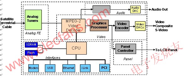
Multiple subsystems have been added to the tuning circuit board. The basic functions can be broadly classified into the following modules:
1. Analog front end (demodulator)
2. Audio / video encoding and decoding (MPEG video decoder / MPEG audio decoder)
3. Various interfaces
4. Display
Almost all the modules shown in the figure above require a clock signal. The typical clock signal range required by the CPU is 30 – 100MHz. The MPEG standard requires a clock input based on 27MHz. Among them, there is a necessary function that requires decoder and encoder synchronization, and this function is implemented by VCXO (voltage controlled crystal oscillator). For the audio clock used as the clock source of the digital-to-analog converter (DAC), the ppm requirement is extremely strict. These frequencies depend on the sampling frequency and oversampling ratio. For various interfaces, the clock signal is determined by their respective standards, such as USB, Ethernet, modem, PCI, PCIExpress, SATA, etc.
The clock of the display depends on the screen size and display standard (high definition (HD): 1080i, 1080p, 720p; standard definition (SD): NTSC, PAL). The basic system of the screen controller subsystem is to convert the input image data to the actual screen size, for example, using a clock such as 74.17582418 MHz.
2. TV system architecture and clock tree implementation
At present, a key decision that designers have to make early in the design is the signal format, including analog or digital signals. A few years ago, the signal link of televisions was still mainly based on analog signals, but today, the digital audio data path is more commonly used. Both digital and analog channels have inherent advantages and disadvantages. However, at present, there is a global inevitable development trend, which requires all signal transmission to use digital technology, and this trend will be realized in stages.
High-definition television transmission uses digital signals, so new TV sets tend to use digital channels. The advantage of using digital transmission is that it is very fault tolerant to noise. On the other hand, analog signals are susceptible to noise. Circuit board designers need to pay special attention to wiring, use differential signals with better signal-to-noise ratio (SNR) performance, or use shielding techniques to avoid signal quality degradation.
Traditional clock tree design method: This method uses a separate crystal / crystal oscillator (XO) for each frequency requirement. The advantage of this method is that the clock can be placed very close to the components, making the wiring simple. However, the drawback of this method is that each crystal / crystal oscillator component must be purchased from the supplier in advance, which does not allow design changes to be made at the final stage. If a frequency changes, it also requires a long delivery cycle, which leads to a delay in the overall progress.
Silicon chip timing solutions: For more than 10 years, the popularity of timing solutions based on phase-locked loops has surpassed traditional clocking methods. Suppliers of silicon chip timing solutions can provide multiple functions not supported by discrete crystals and crystal oscillator components, which can be applied to complex system designs. The trade-off between these two design methods will be discussed below. The main benefit to customers who have switched to this architecture is that it gives customers flexibility in their design options and saves costs.
3. Compared with discrete crystal / crystal oscillator, the advantages of using PLL silicon chip timing solution
1. Cost-One of the driving factors for important decisions in the consumer product market is cost. Every change in system architecture must be economical and cost-effective, so that changes in the architecture can be implemented and the investment paid is reasonable. The most attractive advantage of silicon chip timing solutions is that by integrating several crystals / crystal oscillators together, the overall bill of materials cost can be reduced and the performance level can be maintained, or in some cases increased. In the typical TV antenna circuit board shown in the above figure, 5-6 discrete crystals (each costing 0.12-0.50 USD) are used, and if a silicon chip clock generator that can provide the programmable function of the above frequency If the cost is less than US $ 2.00, it will really add value to the circuit board. In addition to cost being the main driving factor for crystal / crystal oscillator integration, there are other advantages that can be felt by OEMs and end users.
2. Reliability-The crystal is a component based on quartz. Compared with the timing solution based on the phase-locked loop, the failure rate of the crystal is higher. Each reduction of a crystal from the system helps to improve the reliability of the entire system. High integration can also reduce the number of components on the circuit board, obtain the highest stability and achieve a lower rework rate.
3. Crystal availability-Crystals with a frequency range between 10-40 MHz are easy to do. But high-frequency crystals above 40 MHz are more difficult to manufacture and require special manufacturing techniques. This crystal is a high-order overtone crystal with a cost range of $ 1-10. These higher-order crystals are more difficult to purchase. The silicon chip timing solution can use a single low-frequency crystal (or a clock reference signal can be used) to generate multiple high-frequency outputs.
4. Crystal aging-The crystal itself is prone to aging phenomenon, and an error of + -2ppm to + -5ppm will occur every few years. The cause of this aging phenomenon is the impurities present inside the crystal material and on the crystal surface and the mechanical stress between the crystal material and the deposited electrode. Aging may cause the performance of the system using crystals to decline slowly. When using crystals, long-term frequency drift has become a common problem. The silicon chip timing solution based on phase-locked loop can maintain accuracy throughout the product's life.
5. Programmability-Clock generators based on phase-locked loops have built-in programmability and can provide some flexibility in the design phase. These programmable features include not only changes in output frequency, but also the ability to change drive signal strength settings, spread spectrum percentages, and frequency selection through pin programming, which means that the same output can provide different frequencies as needed. The built-in programmability of the system can use the serial I2C interface to change some specific parameters during the design execution process. This feature is attractive to manufacturers that use the same set of frequencies on multiple platforms.
6. Reduce the number of components and save board space-the use of a programmable clock generator helps reduce the number of components on the circuit board through integration. System designers are tending to use fewer components to reduce problems caused by wiring and the need to maintain signal integrity. A clock generator based on a phase-locked loop can use a low-frequency crystal to generate several outputs, so it is extremely valuable for reducing the total number of components and saving valuable board space.
7. Adopt spread spectrum clock to reduce electromagnetic interference-TV antenna circuit board is typically 5-7 layer board, and a special ground layer is used to reduce interference. In order to improve system performance and avoid crosstalk, distortion and signal integrity problems, careful routing of multiple high-speed signals is required. Suppliers of silicon chip timing devices have reduced the design problems of these boards by providing functions such as spread spectrum. For example, spread spectrum can reduce the peak energy of a signal by spreading a high-speed signal.
Electromagnetic interference must be below the limits specified in mandatory standards, such as CISPR 22 or FCC Part 15 Class B. All consumer products must pass strict FCC certification before they can be marketed. Regulatory agencies around the world, such as the United States Communications Commission (FCC), will ensure that mandatory standards are adhered to and that device products cannot emit signals in frequency bands that do not belong to them. Unfortunately, high-speed design solutions with frequency harmonics often encounter problems in this regard. Spread spectrum is a function currently provided by integrated circuit suppliers to solve this interference problem.
The spread spectrum function can reduce or even eliminate the need for ferrite beads, filters, coils, and vibrators that increase the bill of materials cost. If the system fails the electromagnetic compliance test, it will require a lot of effort to redesign. Taking into account the cost of the test and the time wasted in re-engineering, we will recognize the importance of taking these issues into consideration and taking insurance measures, such as adopting the spread spectrum function in advance. With programmability, the spread spectrum function can be turned on when needed and turned off when not needed. This feature is especially useful in development and testing.
8. Inventory management-One of the main challenges currently faced by the procurement team is to manage the inventory, demand and forecasting of each component used in the system. Since each OEM has multiple product platforms and sub-platforms, these platforms and sub-platforms are in different market segments and are specifically targeted at specific target markets, and managing this supply chain is a very heavy job. We can imagine how cumbersome it is to manage 10 crystal products with different frequencies and supplied by different suppliers worldwide. The supplier of silicon chip timing components provides a programmable clock generator, which can be used by designers to generate different frequencies using software during design, thus solving this problem. This programmability not only makes the designer's work easier, but also provides different frequencies to meet the predetermined goals of timing, and also enables the procurement team to purchase the same device products on multiple platforms. If the demand for one of the platforms suddenly increases, the purchasing team can use the purchased devices originally for different platforms. In addition, because there are some features such as pin programming to achieve frequency selection, these components can be used without significantly affecting the design.
9. Perfect synchronous output-some applications may require several clock signals to be copied, and the clocks of these copies are required to be completely synchronized or consistent. This function can be provided by a programmable phase-locked loop device. When using several discrete crystals, it may be more difficult to achieve such synchronization performance.
10. Power management-A clock generator based on a programmable phase-locked loop can meet the special needs of the portable device market, including game consoles, smart phones, personal media players, digital cameras, portable video cameras, etc. In these applications that are sensitive to power consumption, certain frequencies can be selectively turned off by using I2C communication or pin programming technology. For example, in the field of smartphones, not all applications need to run for a long time. When the user wants to use one of the functions, for example, when using the GPS function for directions, this specific frequency can be turned on. Once this function is no longer used, the system can reduce the power of this frequency source to run. In traditional designs using discrete crystals / crystal oscillators, this is not easy to achieve.
4. Why need to reduce the electromagnetic interference of the LCD panel controller
The LCD screen is now ubiquitous and extremely popular, and its applications in our actual lives are beyond our imagination. These include the 3.5-inch touch screens of all the new iPhones you are buying, the Sharp Aquos® TVs you bought during the Thanksgiving sale, or the glittering lights you saw in the bustling area of ​​Las Vegas Street signs, or more commonly, the ThinkPad laptops you use every day-the technology that powers these visual enjoyments is actually LCD technology. The penetration of the LCD panel shows that the technology driving its popularity is mature, and the price of the new model is more reasonable than before.
The requirements for LCD screens are also increasing, and people demand larger panels, less electromagnetic interference, lower power consumption, and higher image quality.
Here, we conduct some detailed analysis of the LCD panel architecture from a higher level. A liquid crystal panel is actually an array of transistors. This array is used to modulate the voltage across the liquid crystal and can therefore control the amount of light passing through the panel. Color display is essentially achieved by using filters that let red, green, or blue light pass through a given pixel. The row driver is connected to the gate of the transistor. The row driver controls which row of pixels is being programmed at any given moment by applying an "on" or "off" voltage. The source of these transistors is connected to the column driver, and the column driver supplies the specific voltage required to achieve the correct pixel brightness.
The timing controller obtains display data from the host and transmits the data to the column driver and row driver through the panel interface. You can also add additional features, such as overdrive to reduce motion blur, enhance the image, and perform gamma correction. The line driver interface uses a transistor logic circuit (TTL) as the signal generation stage. The column driver interface requires a large amount of bandwidth to achieve a clearer display, so different bus architectures are used—typically, swing-suppressed differential signaling (RSDS) is used.
LVDS Transmitter LVDS (Low Voltage Differential Signal) transmitter
Ref Clock
SS Clock Spread Spectrum Clock
LVDS Receiver
Timing Controller
Color Processing
RSDS Transmitter
Row Driver
Column Driver
LCD Panel 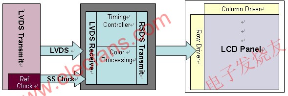
One of the main challenges in panel electronic circuits is to reduce interference to meet the requirements of electromagnetic compatibility (EMC) specifications. Panel manufacturers usually provide different types of panels for different kinds of applications, including televisions, PC monitors, notebook computers, handheld devices, personal entertainment systems, etc. However, panel manufacturers tend to use the same circuit board on all sizes of panels. But how do these manufacturers use limited size 2-layer circuit boards to meet electromagnetic interference (EMI) test requirements? How can they effectively design printed circuit boards (PCBs) for various screen sizes, and also be able to complete projects on time while meeting electromagnetic specifications?
There are several ways to achieve these goals. One is to improve the quality of the printed circuit board material and increase the number of additional circuit board layers using dedicated ground layers. Most printed circuit boards in liquid crystal panels are manufactured using standard FR4 materials. Considering the increased cost, it is not a feasible solution to use more costly printed circuit board materials and add more circuit board layers. Another method to reduce electromagnetic interference is to use filtering, but this method is not a perfect solution that can be applied to all panel sizes. Moreover, every circuit network needs to be filtered. Failure to meet the electromagnetic compatibility test requirements will lead to re-engineering and affect the product's time to market.
As shown in Figure 2, spread-spectrum (SS) clock generators have become a popular way to solve electromagnetic interference problems. Several silicon integrated circuit suppliers, including Cypress Semiconductor Corporation, have been able to supply spread-spectrum clock products for liquid crystal display systems. Its advantage lies in that it can adopt a systematic method to solve the problem of electromagnetic interference in the early stage. The spread spectrum function can be selectively turned on, and the spread spectrum percentage can be adjusted to obtain an appropriate spread to pass the electromagnetic compatibility test. For different size panels, the expansion percentage can also be different, this can be determined according to needs, and the same components are used. Due to the limited board space, these clock products use a very small package size.
Overall, the architecture of digital TVs, including LCD TVs, is constantly evolving, and newer methods are being used to provide high-quality "high-definition" audio and video while maintaining economic rationality for the final market. Digital TV manufacturers are gradually recognizing the value of silicon chip multi-phase-locked loops and spread-spectrum clocking methods in improving performance and accelerating the time to market.
Design and application of multi-phase-locked loop and spread spectrum clock in digital entertainment equipment
With the continuous development of integration technology, the application of silicon chip timing solutions based on phase-locked loops (PLL) is becoming more and more common, providing cleaner and more stable clock selection solutions for design solutions that require multiple frequencies. The purpose of this article is to discuss in detail the value proposition of using silicon chip timing solutions to solve timing design challenges, and compare it with traditional design methods that use multiple independent crystals or crystal oscillators (XOs).