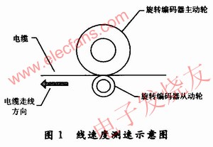
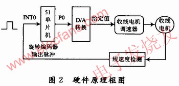
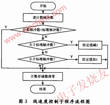
O Introduction In the cable production line, usually need to detect the cable routing speed, used to control the speed of the take-up motor and calculate the cable length. The stability of the cabling process parameters is directly related to the quality of wire and cable. This project is a technical transformation project for a cable factory. The equipment to be transformed is a coiled cable-making machine manufactured by the principle of wire harness. The content of the transformation is to replace all electrical control systems. The pay-off reel of this cable forming machine is fixed, and the take-up reel is fixed on the winch to complete the dual movements of twisting and take-up at the same time. During work, the cable reel movement is completed under the drive of the cable reel DC motor, and the cable is neatly arranged on the cable reel under the drive of the cable arrangement motor. Driven by the large disk motor, the gear box drives the winch to achieve axial rotation and complete the cable twisting movement, which is the key to ensuring the pitch. The linear speed is determined by the rotation speed of the take-up reel. If the speed of the take-up motor is constant, the linear speed of the take-up reel will increase as the take-up shaft becomes thicker. The speed of the take-up motor. 1 System design principle According to the production process requirements of the cable, the routing speed of different types of cables is constant. Usually, the running speed of the cable is detected by the rotary encoder driven by the cable. The schematic diagram of cable speed measurement is shown in Figure 1. In this project, the model of the rotary encoder used is the TRDJ1000 series, which outputs 1 000 pulses per revolution. Therefore, based on the number of pulses detected within a certain period of time, the cable routing speed can be calculated. In actual application, it is installed coaxially with a rotary encoder measuring drive wheel with extremely high processing accuracy and a circumference of 500 mm. During the production process of the cable, the measuring wheel is pulled by friction to rotate, so that the linear displacement (length) of the cable is converted into the pulse digital signal output of the rotary encoder. Assuming that the rotary encoder rotates once, the count pulse number is NP (the number of pulses / revolution), then the angular resolution of the rotary encoder (unit: (°) / piece) is P = 360 / NP Assuming that the radius of the active guide wheel fixed on the rotary shaft of the rotary encoder is rm, the rotary encoder displacement resolution (unit: m / piece) is Ps = 27πr / NP At this time, if the number of count pulses is N (number), the displacement S (unit: m) measured by the rotary encoder is: S = Ps · N The cable routing speed V (unit: m / s) is: V = S / T Where: T is the time it takes to receive N pulses (unit: s). 2 Principles of hardware circuit design The detection circuit uses the AT89C51 microcontroller as the control core. As shown in Figure 2, the pulse output by the rotary encoder, after level conversion, becomes a TTL level pulse of 0 to 5 V, and is sent to the external interrupt INT0 terminal of the AT89 C51 microcontroller. . Every time a pulse is received, the single-chip microcomputer interrupts once, and the count pulse memory is increased by 1. After comparing with the standard pulse value, the P0 port of the single-chip microcomputer outputs the given value digital quantity, and then becomes the given value analog quantity through D / A conversion Give the take-up motor speed governor to control the motor speed. The D / A conversion chip here uses an 8-bit data input and a TLC7226IDW with four analog outputs. If you need to improve the motor speed control accuracy, you can use other 10-bit, 12-bit data input D / A conversion chip. In operation, when the take-up motor drives the cable, the driving wheel of the rotary encoder is rotated, so that the rotary encoder rotates and outputs pulses. The pulse is sent to the photocoupler for isolation, shaping, level conversion, and is sent to the 12 pins of AT89C51. The external interrupt INTO is used to count the pulse. Each time a pulse is received, the MCU executes the external interrupt INT0 subroutine once, and the pulse count memory is incremented. For example, it is read every 1 s at intervals, so that the number of counted pulses can be compared with the standard number of pulses. Therefore, the current linear velocity can be determined. The calculation method of linear velocity is as follows: For example, the linear velocity V is required to be 0.1 m / s. Rotary encoder output pulses per second = V · Np / C Where: C is the circumference of the drive wheel of the rotary encoder (unit: m). Therefore, when the linear velocity is O.1 m / s, the rotary encoder outputs standard pulses per second = 0.1 × 1000 / 0.5 = 200 / s 3 Software design It runs in the timer interrupt and executes once every second in the timer subroutine. That is, check whether the number of pulses received per second is the same as the standard pulse. The linear speed control subroutine is shown in Figure 3. First, read the value of the pulse count memory, compared with the standard pulse number, equal to the standard pulse, the pulse count memory value is cleared, indicating that the line speed is equal to the standard speed; if it is greater than the standard pulse number, it indicates that the line speed is greater than the standard line speed, Therefore, the setpoint of the governor must be reduced by 1 to reduce the speed of the take-up motor; if it is less than the number of standard pulses, it means that the linear speed is less than the standard linear speed. Increase to form a closed-loop linear speed control feedback system to control the rotation speed of the take-up motor so that the linear speed remains constant. 4 Conclusion According to the technological requirements of the cable forming machine, a closed-loop linear speed control system composed of a single chip microcomputer and a rotary encoder is designed, and the design method of the main control program is given. It can also realize the functions of detecting the length of the cable trace and calculating the running time through the software, and display it through the display screen. The above linear speed control system has been successfully applied in actual technological transformation, saving nearly one million yuan in technological transformation funds for the enterprise. The results show that the system has the characteristics of stable and reliable operation, simple circuit, high measurement accuracy, and low cost. It fully meets the requirements of cable production technology. Its simple circuit design and typical control method have high reference value. 4L Deep Fryer,Household Electric Deep Fryer,Extra Filter 4.5L Electric Deep Fryer,Timer Control Electric Deep Fryer Shaoxing Haoda Electrical Appliance Co.,Ltd , https://www.hotplates.nl