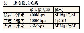
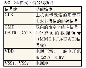
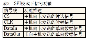
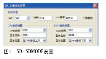
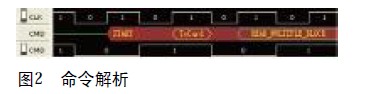
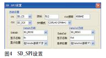
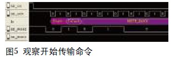
1 Introduction This article refers to the address: http:// We are now in the information age, and electronic devices such as digital cameras and notebook computers have entered thousands of households. And these are inseparable from storage devices. One of the members of the storage device, from the selection tube to the punch card, toner cartridge, CD, floppy disk, tape, solid state drive, etc., stands out – it is the SD card. SD card has a large capacity, low power consumption, small size and light weight, hot swap, and low price. It plays an important role in today's mobile storage. For example, today's notebook computers, digital cameras, mp4 and other digital products have no one. The exception is an SD card reader interface for user convenience. Today we take the LAB7504, a series of logic analyzers produced by Guangzhou Zhiyuan Electronics, as an example to introduce its application in SD card design. 2.SD card introduction The SD card supports three transmission modes: SPI mode (independent sequence input and sequence output), 1-bit SD mode (independent command and data channel, unique transmission format), 4-bit SD mode (supports four-bit wide parallel transmission) ). Table 1 describes the relationship between data rates and patterns. The bus topology of the SD mode is: A host (such as a microcontroller), multiple slaves (cards), and a synchronized star topology. All cards share the clock CLK, power and ground signals. The command line (CMD) and the data line (DAT0~DAT3) are dedicated lines of the card, that is, each card has these signal lines independently. Table 2 describes the signal functions in SD mode. In SPI mode, the host uses the SPI bus to access the card. The first reset command of the microcontroller after the card is powered up can select the card to enter SD mode or SP I mode, but during the power-on of the card, the communication between them The mode cannot be changed to SD mode. Table 3 describes the signal functions in SPI mode. 3. Decoding analysis The protocol of the SD card is more complicated, and the modes are also more. The commands in each mode, the response behavior, the CRC of the data token, etc. are also very complicated. If it is in the design, the R&D personnel need to analyze the logic levels one by one. The efficiency is too low, and it is also easy to make mistakes. The LAB7504 logic analyzer produced by Guangzhou Zhiyuan Electronics Co., Ltd. has SD card SPI mode and SD mode plug-in decoding tool, which can help engineers quickly and intuitively analyze SD. Commands and data on the card bus. The following two modes of decoding plug-ins are introduced separately. SD mode Click the logic analyzer host computer [Tools], [Plug-in Manager], and select "SD Card SD Mode Protocol Analysis". The S D_SDMODE setting dialog box is displayed. Fill in the bus setting options according to the actual situation of the SD card. The bus settings for this acquisition are shown in Figure 1 (cut off the color settings and display settings). Introduction to parameter settings CLK: Select the clock signal to decode the data, representing the CLK clock signal in the protocol. Block Length: Enter the number of blocks in a multi-block transfer. In the process of reading and writing data blocks, there are multiple read and write commands. The user needs to set the number of blocks when reading and writing multiple blocks, and input corresponding numbers in the block length. CLK frequency: Input clock frequency. The clock frequency refers to the frequency at which the clock signal is transmitted, and is set according to the transmission of the clock signal. Wide bus: Select whether or not wide bus transfer. That is, whether the 4-bit SD mode is selected or not, the single bus is the 1-bit SD mode. CMD bus settings: Set command bus parameters. DATA bus settings: Set data bus parameters. Frame color setting: Set the display color of each frame in the package after decoding. Package color setting: Set the display color of the package after decoding. Display mode: Set the display mode of the decoded data, which is hexadecimal, decimal and character format. Let's take a look at the results after decoding through the plugin. As shown in Figure 2, the decoded signal is amplified, you can see the start bit: START; transmission bit: ToCar d; command: READ_MULTIPLE_BLOCK and other information (here there are command parameters, CRC check, end bit and other information is not displayed ). As shown in Figure 3, the result of the data bus decoding, in which the red box is the data start flag. SPI mode Click the logic analyzer host computer [Tools], [Plug-in Manager], and select "SD Card SPI Mode Protocol Analysis". The SD_SPI Settings dialog box is displayed. Fill in the bus setting options according to the actual situation of the SD card. The bus settings for this acquisition are shown in Figure 4 (Truncate color settings and display settings). Introduction to parameter settings CS: Select the chip select signal line to represent the CS chip select signal in the protocol. CLK: Select the clock signal to decode the data, representing the CLK clock signal in the protocol. Block Length: Enter the number of blocks in a multi-block transfer. CLK frequency: The clock frequency of the input CLK signal. SPI mode: Select the mode of SPI decoding, starting from the first or second pulse, sampling on the rising or falling edge. DataIn bus: Set the input bus information in the protocol. DataOut bus: Sets the output bus information in the protocol. Frame color setting: Set the display color of each frame in the package after decoding. Package color setting: Set the display color of the package after decoding. Display mode: Set the display mode of the decoded data, which is hexadecimal, decimal and character format. Due to space limitations, the decoding of the SPI mode is not described too much here. The instructions for decoding the software and the way the data is viewed are similar to those in the SD mode. These readers can use their own applications. Operating experience. Here is a screenshot of the observation start transmission command, as shown in Figure 5, error! The reference source was not found. At the beginning, the information of the command is clear at a glance. 4. Summary Using the SD card analysis plug-in function provided by the logic analyzer software produced by Guangzhou Zhiyuan Electronics Co., Ltd., it can help engineers to leave the analysis of a single logic signal, quickly and intuitively analyze the command data of the transmission process, and quickly find the problem. Improve the efficiency of engineers. At the same time, the LAB7504 provides excellent sample rate and memory capacity, making it easy to find timing issues between communication signals, helping engineers quickly identify and resolve current problems and potential timing hazards.
Offered in the market at the most reasonable rate possible, theMonocrystalline Solar Panel made available by us is known to be highly praised and preferred in the market. Manufactured in accordance with the industry set norms and guidelines, its quality never deteriorates. Its superior performance and service life, is further, owing to the quality raw materials and modern machines used in its making.Offered in the market at the most reasonable rate possible,Solar Panel made available by us is known to be highly praised and preferred in the market. Manufactured in accordance with the industry set norms and guidelines, its quality never deteriorates. Its superior performance and service life, is further, owing to the quality raw materials and modern machines used in its making.
Mono 100W Solar Panel,Mono Solar Panel 100W,Mono Solar Pv Panel 100W,100 Watt Mono Solar Panel Yangzhou Bright Solar Solutions Co., Ltd. , https://www.cnbrightsolar.com