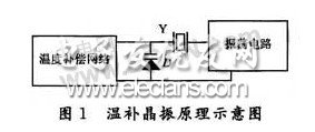
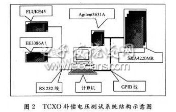
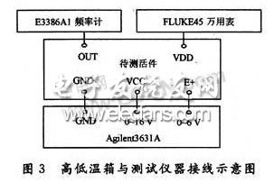
Temperature compensated quartz crystal oscillator (TCXO) is widely used in communication systems, radar navigation systems, precision measurement and control systems, etc. due to its high frequency stability. The temperature-compensated crystal oscillator is composed of a quartz crystal oscillation circuit and a temperature compensation network. Among them, the optimal design of the temperature compensation network is of great significance for improving the temperature-frequency characteristics of the temperature-compensated crystal oscillator and improving the frequency accuracy of the oscillator. The temperature-compensated crystal oscillator is composed of a quartz crystal oscillation circuit and a temperature compensation network. A schematic diagram of a typical temperature-compensated crystal oscillator is shown in Figure 1. The frequency-temperature characteristics of the oscillator are mainly determined by the frequency-temperature characteristics of the crystal resonator. The frequency and temperature characteristics of the commonly used AT-cut crystal resonator are cubic curves. The principle of temperature compensation crystal temperature compensation is to compensate the frequency drift caused by the ambient temperature change of the resonator by changing the load capacitance in the oscillation circuit. . In Figure 1, the voltage applied across the varactor diode D (ie, the compensation voltage) is output by the temperature compensation network. The temperature compensation network automatically adjusts the output voltage with temperature, and the varactor diode capacity changes to cancel the change of the resonator frequency with temperature. , the output frequency can be basically unchanged. From the above principle analysis, the compensation process of the temperature compensation crystal oscillator can be obtained as follows: (1) Test the compensation voltage-temperature curve (VT curve); (2) Calculating the resistance values ​​of the resistors in the thermal network according to the VT curve data; (3) Assembling the temperature compensation network, testing the fT curve of the finished oscillator, and evaluating the compensation effect. It can be seen that obtaining accurate VT curve parameters is a key link in the design and production of temperature-compensated crystal oscillators, which is directly related to the frequency accuracy of the oscillator, and is related to the quality of the finished temperature-compensated crystal oscillator. 2 system hardware composition and testing process The measurement of the temperature compensation network compensation voltage is mostly done manually. Replace the temperature compensation network with a small power DC voltage source, change the temperature to the target point and keep warm, then adjust the voltage source output to make the oscillator output reach the center frequency. At this time, the voltage source output is the compensation voltage of the temperature point; The above operation is repeated at the temperature point to obtain a set of data, that is, VT curve data. This manual measurement method is inefficient, labor cost is high, and manual recording of test data is prone to errors, making it difficult to achieve accurate and rapid quality production. This paper proposes an automatic test method for temperature compensation network compensation voltage, which realizes automatic control and measurement. 2.1 system hardware components The temperature compensation network automatic voltage test system uses the computer as the control core and combines the application software to realize the automatic test of the compensation voltage test process. The system can complete the automatic control of the equipment, automatic test of the instrument, data storage and data analysis, which greatly improves the test speed, saves the working time, and can improve the test accuracy, which has obvious superiority compared with the traditional manual manual test. The system uses a computer as the control center, including high and low temperature boxes, programmable power supplies, digital frequency meters and digital multimeters. The system structure diagram is shown in Figure 2. (1) High and low temperature box S&A4220MR Support GPIB interface program control, meet the test requirements of -50 ~ +80 °C, the measuring circle inside the box is equipped with 50 stations, each station is connected to a semi-finished job with a compensation voltage through 5 wires, respectively connected to the workpiece The GND, VCC, VDD, OUT and E+, high and low temperature boxes are connected to the external instrument as shown in Figure 3. (2) Programmable power supply Agilent 3631A Support GPIB interface program control, to meet independent dual power supply, of which 0 ~ 6 V for E + power supply, its resolution can be up to 2 mV; 0 ~ 25 V for TCXO system to provide working voltage. (3) Digital frequency meter EE3386A1 Support serial port program control for obtaining TCXO output frequency. (4) FLUKE45 multimeter Support serial port program control, used to obtain the output voltage VDD of the TCXO internal three-terminal regulator, and calculate auxiliary data for compensation network analysis.
Special Application safes are safes that are used in special scene and/or with special functions.
Details:
Solid steel construction;
Including data safes, medical safes and jewelry safes;
Electronic & mechanical panels are available;
Equipped with Mechanical Lock for the emergent opening of the safe
Special Application Biometric Fingerprint Treasure Safe,Intelligent Electronic Safe,Biometric Safes,Fingerprint Treasure Safe YONGFA INTELLIGENT TECHNOLOGY SECURITY CO., LTD. , http://www.yongfa-safe.com
1 Temperature compensation crystal temperature compensation principle