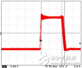
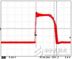
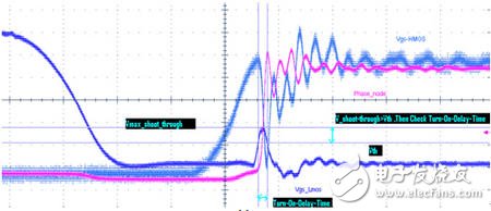
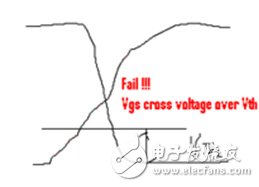
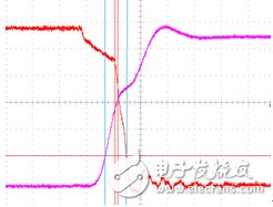
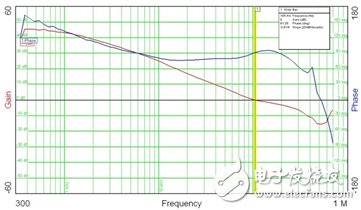
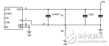
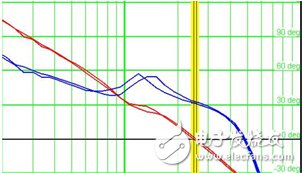
The power measurement of an electronic device is usually measured by a switching power supply (and of course a linear power supply). There are many materials about switching power supply. The content discussed in this article is PWM switching power supply, and it is only a summary of testing experience. It briefly describes some factors that easily cause system failure. Therefore, before reading this article, you have assumed that you have some knowledge of switching power supplies. 1, switching power supply brief Switching Mode Power Supply (often simplified to SMPS) is a high frequency power conversion device. Its function is to convert the voltage through different forms of architecture to the voltage or current required by the user. The topology of the switching power supply refers to the form of the switching power supply circuit. Generally, it is divided into isolated and non-isolated converters according to whether the output ground line is electrically isolated from the input ground line. Non-isolated, that is, the input end and the output end are connected, there is no isolation measure, and most common DC/DC converters are of this type. The so-called isolation means that the input end and the output end are not directly connected in the circuit, and the energy transfer is performed by the electromagnetic conversion method using the isolation transformer, and the input end and the output end are completely electrically isolated. For switching converters, there are only three basic topologies, namely: Buck (buck) Boost Buck-Boost The three basic topologies are determined by the way the inductors are connected. If the inductor is placed at the output, it is the Buck topology; when the inductor is placed at the input, it is the Boost topology. When the inductor is connected to ground, it is the Buck-Boost topology. 2, the key parameter test that is easy to cause system failure The following test items refer to the results of tests under static load conditions, and only noise tests require dynamic loads. 2.1 Phase point jitter Figure 1 For a typical PWM switching power supply, if the phase point jitter is too large, the system will usually be unstable (related to the phase margin mentioned later). For a 200~500K PWM switching power supply, the typical jitter value should be below 1 ns. 2.2 Phase point collapse Sometimes the engineer measures the waveform below, which is a typical phenomenon of inductor saturation. For engineers with insufficient experience, they are often ignored. Inductance saturation causes the inductor value to drop sharply, similar to a short circuit, which causes a sharp increase in current. MOS transistors tend to burn out due to a sharp increase in temperature. At this time, it is necessary to replace the inductor with a larger saturation current. Figure II 2.3 Shoot through test The purpose of the test is to see if the MOSFET is turned on, and if the lower tube is turned on at the same time, causing the power supply to directly conduct to the ground and cause a short circuit. The blue curve (Vgs_Lmos) shown in Figure 3 is the lower tube that is brought up while the upper tube is turned on. If the peak of the blue curve is raised beyond the Vth requirement of the MOS tube, the duration (DuraTIon) ) also exceeds the datasheet requirements, so there is a risk of simultaneous conduction. Of course, this is the most common situation for everyone. Figure III There are a lot of people who will ignore this situation, and even some experienced power test engineers. The following group 4 is the waveform when the lower tube is opened and the upper tube is closed (Figure 4-1 is a schematic diagram, Figure 4-2 shows the actual test diagram). Although it is not brought up at the same time, please note that the upper and lower tubes have a crossover phenomenon, and the level of the intersection is much higher than the Vth value specified by the MOS tube, which is a serious shoot through phenomenon. The most direct consequence is that the MOS tube burned out! Pic 4-1 Figure 4-2 2.4 phase margin and bandwidth (phase margin and bandwidth) Phase margin and bandwidth are items that many companies have not tested (especially smaller companies are limited by instruments), but this is a very important test. Whether the power system is stable, whether it can work effectively for a long time (3 years or more), phase margin and bandwidth can play a decisive role to a large extent. Many companies rely entirely on the recommended values ​​in the reference design given by the power chip manufacturer, but there are often significant differences with your design, which poses a significant potential risk. If the system is an unstable system, reflected in some power test items, you will see the following major problems. The Noise test of the power supply passed, but the power supply is still unstable. Performance as a functional test fail. Often engineers have said that my power supply is very small when debugging, adding a lot of capacitors, why not run? In fact, his closed-loop system is inherently unstable. Phase point jitter is too big. This is a typical instability phenomenon. The transient response is too large. The most stupid way is to add a lot of capacitors to meet the transient response requirements. For low-cost products, this is money. If you haven't tested the Bode plot of the loop gain of the system in the right way, how do you get started debugging these projects and let him pass the test? Only come back and forth to experiment. Then come back and forth to run the functional test. Oh, my god, a huge workload. Moreover, for some low-cost products, aluminum electrolytic capacitors, MLCC capacitors and other low-cost solutions (inductance, resistance values ​​are basically unchanged) are often used. The capacitance of these capacitors decreases over time. For example, MLCC, the system operates at normal temperature for two to three years, the capacitance will change to half of the original. The change of this half capacitance will have a great impact on the stability of the system, which is also an important reason why many low-priced products are unreliable. Does that mean that the higher the price, the better the capacitors are, the better. Of course not. This is why you want to test the phase margin. You need to debug a reasonable set of values ​​that cover both full and half capacitance requirements. This can also achieve low prices and high quality. According to the Nyquist theorem for system stability requirements, the specification requires a closed-loop system with a phase margin of at least 60 degrees, and 45 to 60 degrees can be considered as a minimum limit. For bandwidth, the switching power supply of 200~500K is required to have a switching frequency of 10%~30%. From the stability of the switching power supply, the lower the bandwidth, the easier the power supply is stable. From the dynamic indicators of the switching power supply, the higher the bandwidth, the better the dynamic performance of the power supply. Figure 5 below shows a typical Bode plot: Figure 5 It is also very important that, in addition to the PWM switching power supply, there are many linear power supplies (LDOs) whose compensation network is external to the chip, and a similar loop gain Bode plot test is also performed to ensure its stability. LDO testing is easy for most manufacturers to ignore. For example, the circuit shown in Figure 6 below, many people will directly measure the completion of the noise. Figure 6 The phase margin we are likely to see cannot meet the requirements. As shown in Figure 7 below, it is only about 30 degrees. At this time, only the debugging of different parameters can get better results. Thereby meeting the requirements of system stability. Figure 7 2.5 power ripple (ripple) and noise (noise) Power supply ripple and noise appear to be the simplest items in power testing. But it may also have a big impact on your test results and features. The first is ripple. When we test, we just see if it meets the specifications, such as 30mV. Sometimes, the ripple is related to the PLL of the system. If your PLL jitter is not enough, consider further reducing the ripple. Noise, some people will ask, why is my system noise and his system noise basically a range, but my system will run fail? First of all, we have to rule out the reasons for the stability of the system mentioned above, then, pro, have you ever done an FFT with an oscilloscope, and see the difference between the same noise in the frequency domain? Join the power technology [group] to get more technical information, preface topics, and the latest information (the latest technical information download, please click to share)
Epoxy resin seal type NTC Temperature Sensor with the properties of good stability, fast response, temperature resistance, convenient to use, has been already applied to air conditioner, automotive, electrical appliance and induction cooker. Temperature range is from -30°C to 105°C.
Epoxy Resin Seal Sensor Epoxy Resin Seal Sensor,Stability Sensor,Greenhouse Sensors,Bus Sensor Feyvan Electronics Technology Co., Ltd. , http://www.fv-cable-assembly.com