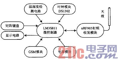
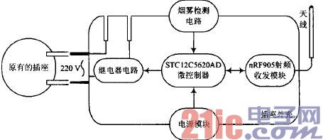
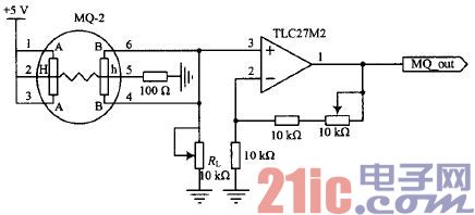
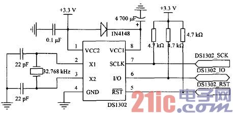
In recent years, the Internet of Things technology has developed rapidly, and the level of informationization in the whole society has continuously improved. Smart home is one of the main applications of the Internet of Things, and has become a hot research field and the future development direction of home life. It can provide users with a comfortable and convenient living environment. However, since most of the related products on the market are expensive, the penetration rate is still low. In the past, exploration and development often stayed on the transformation of electrical equipment itself. This attempt made smart home products once a luxury. This paper introduces a power control system, which is an important part of smart home. It realizes the remote automatic control function without changing the original electrical equipment. This article refers to the address: http:// 1 system structure The power control system is composed of a remote controller and a socket node, and its working principle is shown in FIG. 1 . When the user is at home, the socket is controlled by radio frequency through the remote controller. After receiving the signal, the socket node decodes by the microcontroller, and according to the result, the specific number of sockets are turned on and off, so that the connected electrical appliances are activated or turned off. When the user is far away from the residence, the mobile phone short message can be sent to the remote controller through the GSM network. After the microcontroller reads the information, the information is transmitted to the indoor wireless network through the radio frequency chip, so that the socket at the corresponding address is controlled. . It can be seen that the remote controller belongs to the gateway node in the whole smart home system. On the one hand, it forms an indoor radio frequency local area network with the socket node, and on the other hand, it is connected with the GSM network, and extends the remote control distance. The internal structure of the remote control is shown in Figure 2. It includes the temperature and humidity detection circuit, clock module, nRF905 RF transceiver module, GSM module and other functional circuits. These modules are connected to the control core LM3S811. The microcontroller uses the ARM Coaex-M3 architecture. Due to the high-density Thumb-2 instruction set, the memory overhead is greatly reduced, and the migration of the operating system is more convenient. Figure 1 How the remote control socket works Figure 2 Remote control block diagram The socket node mainly realizes the radio frequency communication with the remote controller and the on/off control of the relay, and its structural block diagram is shown in FIG. 3. Smoke sensors in the socket are used to prevent fire hazards. Once smoke or flammable gas is detected, the corresponding relay on the socket will be disconnected and reported to the remote controller through the RF transceiver module. After receiving the information, the remote controller will promptly remind the user to take corresponding measures through the SMS function of the GSM module. Prevent the occurrence of danger or further expansion of property damage. Due to the small amount of work at the socket end, the system uses the STC12C5620AD microcontroller as the main control chip of the socket end in terms of cost and performance. Figure 3 block node structure block diagram 2 hardware circuit design 2.1 Temperature and Humidity Detection Circuit The system uses the temperature sensor LM35 and the humidity measurement module CHM-02 for environmental monitoring. The voltage output of the LM35 is linear with Celsius temperature and can achieve ±1/4°C measurement accuracy at room temperature without calibration. The CHM-02 module can detect humidity in the range of 20~95% RH at 0~70 °C, and the measurement accuracy at room temperature is 5% RH. The interface diagram of the temperature and humidity sensor and the MCU is shown in Figure 4. Since the analog signals output by the two sensors are within the detection range of the MCU's on-chip A/D sampling circuit, the outputs of the two are directly connected to the two ADC pins of the MCU. The use of analog sensors not only makes full use of the controller's on-chip resources, but also improves the utilization of subroutines. Figure 4 Schematic diagram of the interface between the temperature and humidity sensor and the MCU 2.2 Smoke detection circuit The smoke sensor MQ-2 is based on the electrochemical characteristics of SnO: and has good detection sensitivity for flammable gases and soot. The schematic diagram of the smoke detection circuit is shown in Figure 5. MQ.2 needs to preheat the Hh poles of the internal heating wire before normal operation. In order to prevent the internal signal line temperature from being too high due to excessive heating current, the heating wire is connected in series with the 100 Q resistor. When the smoke or flammable gas in the environment exceeds the warning threshold, the conductivity between the two poles of the sensor AB increases rapidly, and the voltage obtained by the load resistance m connected in series increases accordingly. After the voltage signal is amplified by the low-power operational amplifier TLC27M2, An analog output corresponding to the concentration of smoke or flammable gas is obtained, which is finally quantized by the ADC module of the controller. Figure 5 Schematic diagram of the smoke detection circuit 2.3 clock module In addition to displaying the system time, the clock module can also turn on and off the timing of a single outlet. The schematic diagram of the clock circuit is shown in Figure 6. The DS1302 communicates with the MCU in serial mode. To ensure the stability of signal transmission, the interface has been pulled up. The chip is powered by dual power supply. When the main power supply is working normally, it can charge the standby power supply with fine current; in the case of power failure, the backup power supply is started to avoid the clock stagnation caused by sudden power failure. The remote control is powered by a lithium battery, considering the ease of use. The DS1302's main power pin, VCC2, is connected to the 3.3 V output of the integrated regulator, while the alternate supply pin, VCC1, is connected in series with the 4700 μF capacitor, and the two supply pins are diode-isolated. Since the power consumption of the chip is very low, the discharge of the capacitor can temporarily maintain the operation of the chip during the process of replacing the battery. Figure 6 clock circuit schematic 2.4 RF Transceiver Module nRF905 The RF transceiver module is a bridge connecting the socket to the remote controller. The nRF905 integrated transceiver can be configured for use in three ISM bands with low power consumption. All the nodes in the system are set in the 433 MHz band. The schematic diagram of the RF transceiver circuit is shown in Figure 7. The SMA interface is used to connect a single-ended antenna with a characteristic impedance of 5O Ω, which is beneficial to the omnidirectional radiation of the signal. . The single-ended antenna is also called an unbalanced antenna, and its main reference point is signal ground, while the antenna interface of nRF905 (pins ANT1 and ANT2) is a differential RF output port. In order to maintain the signal balance and ensure the impedance matching of the two ports, a balun (balanced monthly balance) circuit is added between the two to adjust the characteristics of the chip output. Figure 7 RF transceiver circuit 2.5 GSM communication module Combining the short-range RF network with the GSM technology not only makes the short-range RF network configuration flexible, but also takes advantage of the GSM technology in communication distance. The core of the GSM communication circuit is the SIM300 module, and its peripheral circuit is shown in Figure 8. Figure 8 GSM communication circuit schematic The schematic SIM300 communicates with the MCU through the serial port, and a 22 Ω resistor connected in series between the module and the SIM card is used for impedance matching. In order to ensure the transmission quality of the signal, the SIM card data line is pulled up, and the SMF05C type static suppressor connected in parallel with the pin is used for electrostatic protection. A 100 μF tantalum capacitor and a 1 μF ceramic capacitor connected in parallel between the power supply and ground are used to remove low frequency glitch and to some extent have high frequency characteristics. Pressing the S1 button causes the potential of the PWRKEY pin to be pulled low for about 2 s to complete the power-up and power-down of the module. The current state is indicated by the LEDs connected in series on the VDD_EXT pin. In order to facilitate the program control, a triode switch circuit is added on the basis of the original button. When the module works abnormally, the state of the PWR port can be rewritten by software to realize the automatic reset of the SIM300. 3 software design The remote control and the socket are the nodes of the entire RF wireless network, but the difference in hardware structure determines the difference in function and status between the two, and also makes the difference in the way of software design. 3.1 Remote control node program design The remote control is the control core of the system and the link between the user and the socket. Therefore, there are many concurrent modules in the program and the tasks are heavy. Considering that the ARM processor used in the remote control can provide full support for the operating system, using the μC/OS-II operating system to schedule multiple tasks in the node can effectively ensure the real-time performance and stability of the system. Conducive to the expansion of functions. Before the operating system is transplanted, the tasks need to be divided. Each function corresponds to one system task. At the same time, the problem of excessively thinning and frequent scheduling should be avoided. The program flow of the remote controller node is shown in Figure 9. It contains 7 tasks, and the tasks are synchronized and communicated by means of semaphores, message queues, message mailboxes, and the like. From the user's perspective, these tasks are performed concurrently. Figure 9 remote control node program flow chart Key scan tasks have the highest priority among all user tasks. Reading the key value of the user input by interrupting, the data is stored in the message mailbox KeyMbox, if the number key 1-6 is pressed, the radio frequency sending task is notified; if the clock setting button is pressed, the clock adjustment is performed or Timer settings. The clock timing task is used to obtain the clock output value of the DS1302. After the timing time arrives, a message is sent to notify the RF transmission task to be processed, and the hang is automatically completed after completion. The radio frequency transmission task is to send an on/off control signal to the corresponding numbered socket by radio frequency according to the control code obtained in other tasks, and then wait for the socket end to return the action information. If there is no feedback after timeout, it will be resent once, and the task will hang after resending 3 times. The dangerous alarm task needs to pass the same frequency carrier detection. After the address matching is confirmed, the RF signal is received, and then the information is sent to the mailbox. After decoding and confirming the danger alarm identifier, the user is notified by short message through the GSM module. The SMS receiving task is responsible for receiving the user's text message and storing it in the message mailbox GSMMbox. Through the AT command "AT+CMGR=I", only the short message with sequence number 1 is read at a time, and after successfully extracting the control code (including the socket ID number and the switch action code), the piece of information is deleted and transmitted to the radio frequency transmission task. news. The environmental monitoring task is responsible for cyclic sampling of indoor temperature and humidity information. Although the linearity of the temperature sensor is good, the external environment has a great influence on the humidity sensor, and the output voltage value needs to be linearized. The data is stored in the message queue and the final result is the arithmetic mean of the 3 measurements. The liquid crystal display task has the lowest priority. After the above tasks are completed, it is responsible for displaying the final status of each socket, clock information, and indoor temperature and humidity measurement results. 3.2 socket node programming The program flow of the socket node is shown in Figure 10. The most important task is to realize the reception and transmission of RF signals. When there is no smoke alarm, nRF905 enters the receiving mode and listens to the channel; if the same frequency carrier is detected and the data packet address is valid, the receiving is started; when the CRC check result is correct, the hardware will remove the preamble of the data packet and the school. The code and address code are checked, and the MCU data is notified to be ready, and the MCU reads the received information through the SPI serial bus. Figure 1O socket node program flow chart RF signal transmission is essentially the inverse of reception. When the nRF905 enters the standby mode, the MCU transmits the address and data information to the transmit register of the radio frequency chip, and simultaneously starts the chip to enter the radio frequency transmission mode, and then the on-chip hardware automatically completes the task of packing, encoding, modulating, and transmitting the data. After the transmission of one frame of data is finished, the RF chip goes into standby mode and waits for the next activation. Each receiving or transmitting process of the RF circuit is accompanied by a turn-on or turn-off action of the relay. By default, the smoke sensor is enabled. In order to prevent the user from ignoring the smoke in the room, the smoke detection function can also be set to invalid. 4 Testing and analysis On-site testing was conducted in the house shown in Fig. 11, and six sockets and one remote controller were placed in the seven areas A to G. In order to assess the system's immunity to interference, two sources of interference were placed at the junction of each region at frequencies of 432 MHz and 434 MHz. Change the position of the remote control, remotely control the 6 sockets 200 times, and record the feedback signal at the socket end. If an error message is returned or no feedback is returned, it is recorded as a packet loss. Figure 11 Test site network node distribution map It is found that the average error rate of the remote control in the two areas C and E is slightly higher than other areas; when the remote control is in the G area, the average bit error rate is the lowest and the effect is the best. 5 Conclusion The system realizes the intelligent wireless control of the household socket. On the basis of not changing the internal structure of the original home appliance, the user can control the on-off state of the socket through radio frequency, short message, timing and the like. When a fire or flammable gas leaks in the room, the outlet can be automatically powered off. The whole system has no special requirements for the control object, and it has strong adaptability, and it is a cheap smart home solution. Transformer And Frequency Converter,3 Phase Inverter Air Conditioner,Inverter Vs Generator,Voltage And Frequency Converter Wuxi Trenty Machinery & Equipment Co., Ltd. , https://www.elec-inverter.com


Frequency inverters for 3-phase asynchronous motors from 0.75 to 800 kW, variable torque applications