The descriptions and calls of each module in chipscope are described in detail in the above references, and will not be described in detail here. Here is just a simple example, to illustrate how I can directly call chipscope Pro Analyzer in ISE for online logic analysis. `TImescale 1ns / 1ps # PlanAhead Generated physical constraints NET "clk" LOC = P55; Next, the code is synthesized, and the core of the Chipscope is created after the error. First click Project---New Source Wizard in the ISE Project Navigator, select the Chipscope DefiniTIon and Connection Wizard, enter the file name, and click Next to produce the .cdc file, as shown in Figure 1. Cat Litter Box,Cat Star Box,Covered Cat Litter Box,Appearance Cat Litter Box Sensen Group Co., Ltd.  , https://www.sunsunglobal.com
First create a project in ISE and enter the following code:
//////////////////////////////////////////////////////////// ////////////////////////////////////
// Company:
// Engineer:
//
// Create Date: 21:26:06 02/26/2010
// Design Name:
// Module Name: mycounter
// Project Name:
// Target Devices:
// Tool versions:
// DescripTIon:
//
// Dependencies:
//
// Revision:
// Revision 0.01 - File Created
// AddiTIonal Comments:
//
//////////////////////////////////////////////////////////// ////////////////////////////////////
Module mycounter(
Input clk,
// input reset,
Output sout
);
Reg [19:0] cnt=0;
Always @(posedge clk)begin
/* if(!reset)
Cnt<=0;
Else*/
Cnt<=cnt+1;
End
Assign sout=cnt[19];
Endmodule
Here, for the sake of simplicity, signals such as synchronous reset are also masked. I am using a self-made Spartan3 board, where FPGA selects Xilinx's XC3S400-TQC144G; PROM selects Xilinx's XCF02SV0G20C, FPGA's clock pin is P55; and ISE suite uses version 12.2. Then assign the I/O pins in PlanAhead as follows:
//NET "reset" LOC = P11;
NET "sout" LOC = P12; 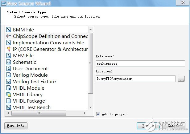
Call chipscope directly in ISE for online logic analysis (2)
Figure 1 production chipscope file
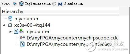
Then double-click the .cdc file you just created in the project file view to enter the Chipscope settings interface, as shown in Figure 2. Figure 2 project file view
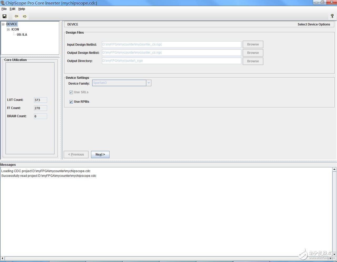
Entering Chipscope, the interface of the ICON core shown in Figure 3 first appears. Figure 3 ICON interface
After clicking Next twice, you will enter the trigger parameter setting interface of the ILA core. The meaning of "trigger" is naturally, under what conditions, the "oscilloscope" is enabled to acquire waveforms. Here the trigger width is chosen to be 20 (because reg [19:0] cnt is defined in the previous program), the matching method is selected as "basic", and the rest of the parameters are generally not required to be changed in a simple design (more complicated Settings can be found in the reference).