This paper is based on the 32-bit embedded SoC of the ARM7TDMI core independently developed by the National ASIC System Engineering Technology Research Center of Southeast University. The SEP3203 processor adopts the G.721 standard ADPCM algorithm to realize the real-time codec of voice signals. Processing applications provide an effective embedded solution. This article refers to the address: http:// 1 Overview of the G.721 standard In 1937, AH Reeves proposed pulse code modulation (PCM), which pioneered the process of voice digital communication. In the early 1980s, CCITT began to study non-PCM coding algorithms below 64 Kb/s, and successively adopted coding standards such as G.721, G.728, and G.729. Among them, the G.721 protocol, as a typical algorithm of ADPCM, not only has the same voice quality as PCM, but also has a simple algorithm structure and excellent error-resistance performance, in satellite, submarine cable and portable digital voice equipment. widely used. A simplified block diagram of the G.721 algorithm is shown in Figure 1. The encoding process: 1 Calculate the difference E(k)=Sl(k)-Se(k) of Sl(k) and the adaptive predictor output Se(k); 2 Quantifying E(k) by an adaptive quantization module to obtain an ADPCM codeword I(k); 3 calculating the quantized differential prediction signal Dq(k) by I(k) through an adaptive inverse quantization module; 4 updating the prediction filter coefficients according to the reconstruction signals Sr(k)=Se(k)+Dq(k) and Dq(k); 5 Using the new coefficient, calculate Se(k+1), repeat the above five steps, and compress the next voice sample data. Decoding process: 1 obtaining Dq(k) and Se(k) by adaptive inverse quantization and adaptive prediction to obtain a speech reconstruction signal Sr(k); 2 performing PCM format conversion on the reconstructed signal Sr(k) to obtain a PCM code word Sp(k); 3 Update the prediction filter coefficients in the same way as the encoder; 4 To achieve two-way communication, adjust Sp(k) synchronously; 5 Repeat the above 5 steps with the new filter coefficients to decode the next I(k). 2 chip introduction The SEP3203 chip is the core of the system processing, and the overall structure block diagram is shown in Figure 2. The chip is a 32-bit SoC based on ARM7TDMI designed by the National ASIC Engineering Technology Research Center of Southeast University. It adopts AMBA2.0 standard and 0.25μm CMOS technology, mainly for embedded low-end handheld devices. On-chip AC97 controller, external memory interface EMI, 6-channel DMAC, TIMER, PMU, INTC and other modules are available. Among them, the modules used in the voice system are: EMI, which is responsible for controlling external access; on-chip memory eSRAM for optimizing time-consuming core code; AC97, providing AC97 standard audio interface; DMAC, for implementing large data DMA Transfer. 3 system design 3.1 Hardware System The hardware system block diagram is shown in Figure 3. The dotted line frame is an on-chip module; the outside of the frame is an off-chip device, including external memory (SDRAM/SRAM/Flash, etc.), CODEC, and the like. Philips' UCB1400 acts as a CODEC. The following is the working process of the system. 1 code. The CODEC samples the voice data and temporarily stores it in the input FIFO of the AC97. Then, the data is transferred to the specified storage area by the DMAC through the interrupt mode. Under the control of the ARM7TDMI, the G.721 encoding program is run to compress the voice PCM data into ADPCM codes. 2 decoding. The G.721 decoding program is run to decode the ADPCM code in the memory into a PCM code. After each frame of data is decoded, the DMAC transfers the data to the output FIFO of the AC97 through the interrupt mode, and drives the playback device (headphone, speaker, etc.) through the CODEC. According to the real-time needs of voice, set the UCB1400 sampling rate to 8 kb/s. The chip uses 16 bits to represent a sample point, so the sampling rate is 128 kb/s. After encoding, each sample point is represented by 4 bits, so the transmission rate is 32 kb/s. 3.2 Software System The software flow is shown in Figure 4. Each frame of data is 64 samples, a total of 128 bytes, 16-bit representation of the PCM code, encoded 32-byte, 4-bit ADPCM code. (1) Coding First initialize the system, including configuration of modules such as AC97, CODEC, and DMAC, and initialization of state variables. Then, the first frame of speech data is sampled, the sampling ends to enter the DMA interrupt, the DMAC is configured again in the interrupt processing, a new sample transmission is triggered, and the data just sampled is encoded. Since the encoding is performed by the kernel and the sampling is done by the CODEC and DMA, the encoding of the Kth frame and the sampling of the K+1th frame are performed concurrently. (2) decoding Similar to the encoding process, the system is first initialized and then the first frame of audio data is decoded. After decoding the configuration DMAC, the trigger data is transmitted to the AC97 output FIFO, and the recording is played through the playback device. Similarly, decoding the K+1th frame data and playing the Kth frame data concurrently. This design uses a "double Buffer" mechanism to buffer data. "Double Buffer" means that two frame buffers are opened for Buf0 and Buf1, and the buffer flag Flg is initially zero. When encoding, the first frame data is sampled, and the DMA transfers data from the AC97 input FIFO to Buf0. After the transfer, Flg=1 is set, and the encoder takes the data encoding from Buf0. At the same time, the DMA transfers the new data to Buf1. Repeatedly, each frame of data is sampled, set Flg=!Flg, the encoder takes the data encoding from the Buf!Flg buffer, and the destination address of the DMA transfer sample data is Buf Flg, thus realizing the K+1 frame data sampling and the Kth Frame data is encoded concurrently. As long as the encoding speed is higher than the sampling speed, no data coverage will occur. The processing is as follows (the situation is similar when decoding): The real-time requirements of voice processing are very high. Otherwise, if the data processing speed cannot keep up with the speed of voice change, the data that has just been sampled during the recording will overwrite the data that was first collected but not processed; when playing, the playback will occur. The speed is slower than the actual voice. Of course, if you use a large enough buffer, you can avoid the problem of recording, but the problem of playback is unavoidable. At the same time, since storage resources are invaluable to embedded systems, this solution has no practical value. The "double Buffer" mechanism introduced above enables the sampling and encoding, decoding and playback to be mutually independent and concurrently executed, and easy to control; but to meet the real-time requirements, the codec speed must be matched with the sampling and coding. The requirements for playback. The voice rate is 8 KB/s, and one sample point in the system is represented by 16 bits, so the codec speed can't be lower than 16 KB/s (that is, at least 16 KB of PCM code per second, at least 16 KB per second). PCM code). Table 1 shows the time taken to process a 512 KB PCM code (corresponding to 128 KB of ADPCM code) without testing the bare metal before the system is optimized. This test was performed using the SoC internal timer TIMER, see references. The test results show that the real-time requirements of the voice are not met before the system optimization. However, the 20K resources of SEP3203 are limited, and it is impossible or necessary to put all the code in it. The ARM integrated development tool provides a Profile function that allows statistical analysis of the entire program to get the percentage of time spent on each part of the code (mainly in standard C functions) as a percentage of the total system time. Through the profile analysis of the software system, the percentage of each codec library function in the total codec time is obtained, and the main part is listed in Table 3. After the memory image is taken, the target code rec_esram.o (about 1.5 KB) of rec_esram.c is loaded into eSRAM (start address is 0x1fff0000). Table 4 shows the codec speed test results after eSRAM optimization. Conclusion Real-time performance is very important when designing an embedded system for multimedia applications. This paper proposes a design scheme of the speech processing system in SoC based on ARM7TDMI core, and optimizes the system performance according to the characteristics of eSRAM. The test of the prototype shows that the system has a coding rate of 19.88 KB/s and a decoding rate of 22.68 KB/s with a frequency of 70 MHz and an operating system, which meets the real-time requirements of the voice system. Moreover, if voice processing is used as a subsystem application of the prototype, its hardware design also supports the functions of MP3 playback and LCD touch screen, achieving the purpose of reducing the system board area and reducing the overall machine cost, and is an efficient and inexpensive design solution.
3D Virtual Reality Functional Case is a phone case for Iphone6s/7/8, 6/7/8 plus, Iphone X and Galaxy S8/S8+,S9/S9+ and note.You can use 3D Virtual Reality case to watch 3D movies, 3D games on your smartphone, after using, you can take it off and put it on the back to protect your smartphone as a protective phone case!
You can download"Mplayer3D" application from APP store, this APP can provide many 3D movies, you can also watch 3D movies and vedios on Youtube, if you have our phone case, you have a 3D movie theather with you.
3D Virtual Reality Functional Case 3D Virtual Reality Functional Case,Iphone 7 3D Virtual Reality Functional Case,Iphone X 3D Virtual Reality Functional Case,Iphone 8 3D Virtual Reality Functional Case iSID Korea Co., Ltd , http://www.isidsnap3d.com
Figure 1. Simplified block diagram of the G.721 encoder and decoder 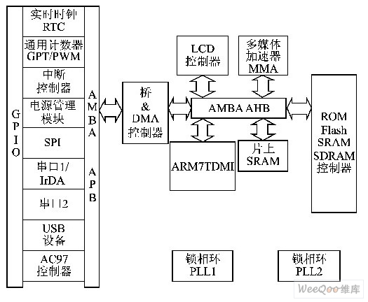
Figure 2 SEP3203 chip structure block diagram 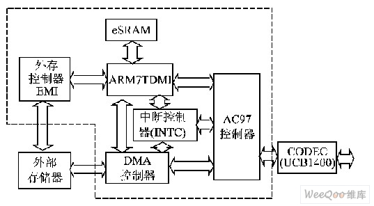
Figure 3 Speech Processing Hardware System Block Diagram 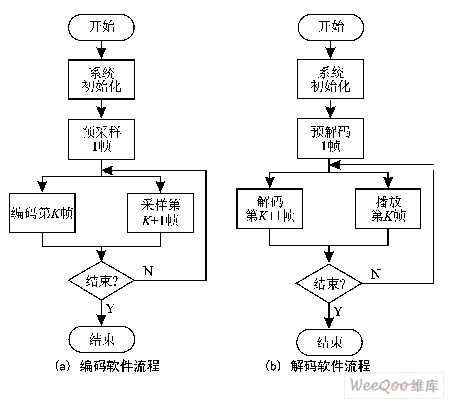
Figure 4 Software flow of codec 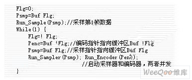
4 performance optimization 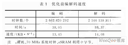
At this point, the system object code is running in SDRAM. The SEP3203 provides a useful module - on-chip high-speed memory eSRAM. eSRAM access speed is very fast, can reach 0.89 MIPS / MHz, so the system performance is greatly optimized, and SDRAM can only have about 1/3 of its performance. Table 2 compares the performance of SDRAM and eSRAM with a 50 MHz clock and 32-bit ARM instructions. The meaning of each indicator can be found in the references. 
The above three functions take up nearly 80% of the time in the total codec time (Quan(), Fmult(), Update() functions are quantization table lookup, fixed point floating point multiplication, state variable update), These code optimizations will significantly increase the speed of the codec. Integrate these function code into the file rec_esram.c, then load the remap.scf file for memory imaging (the *.scf file is the link script file provided by the ARM ADS integrated development tool). 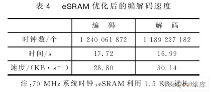
Voice system performance was also tested in the presence of an operating system, as listed in Table 5. The operating system is ASIXOS for embedded applications independently developed by Southeast University's ASIC Engineering Technology and Research Center. It provides graphical user interface, network, clock, real-time interrupt management and other clear application development interfaces. The voice system is an application in the OS environment with a separate user interface and underlying services. Due to space limitations, this article will not be detailed. 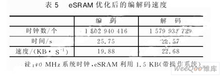
It can be seen from the above test that after eSRAM optimization, whether on the bare machine or in the case of an operating system, the codec speed can meet the real-time needs of the voice and meet the design requirements.


