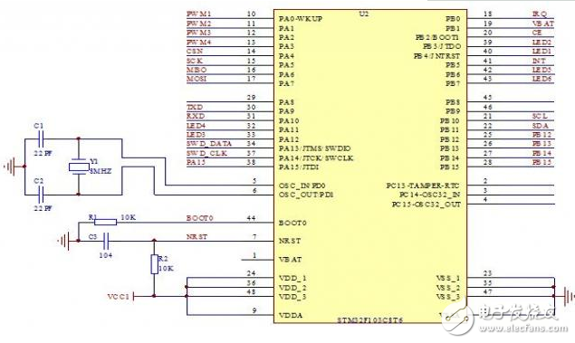
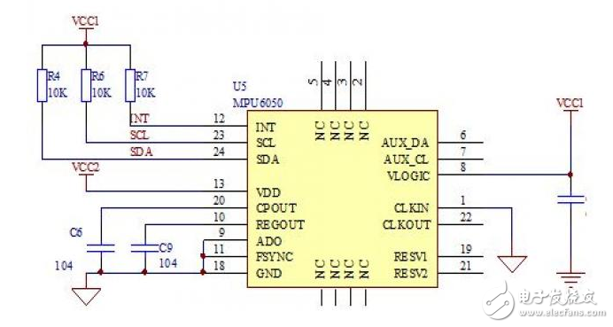
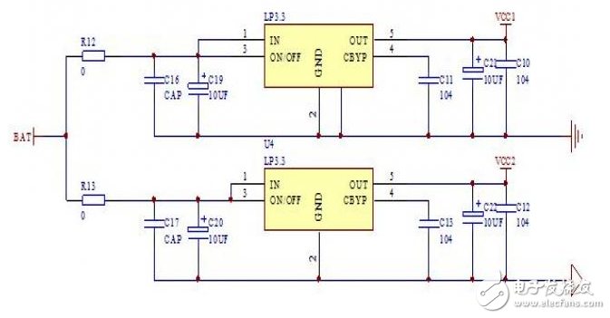
Introduction The quadcopter is a compact and versatile aircraft capable of vertical takeoff and landing. Compared to traditional aircraft, it offers advantages such as a simpler structure, lower failure rate, and greater lift per unit volume. It finds applications in both military and civilian fields, making it ideal for operations in confined spaces. Due to its wide range of potential uses, the quadcopter has become a popular subject for research, attracting many scholars and becoming a growing area of interest globally. This design implements a basic four-axis system using inertial measurement unit (IMU) attitude acquisition technology, PID motor control algorithms, 2.4G wireless remote communication, and high-speed hollow-cup DC motor drive technology. The system consists of two main parts: the flight control unit and the remote control unit. The flight control part integrates the frame with the control core to enhance system stability. The remote control part uses an analog joystick for intuitive operation, while the 2.4G wireless module ensures reliable data transmission between the two units. The flight control board is powered by an STM32 microcontroller, which works with the MPU6050 motion sensor for three-axis gyroscope and accelerometer data. The system uses PWM control based on PID algorithms to drive the motors and achieve remote control functionality. The hardware design of the system includes the remote control board and the flight control board. The remote control board is designed in the shape of a game controller, featuring a four-way joystick and a 2.4G wireless module for data transmission. The flight control board uses an integrated design where the processor and motor are combined on a single circuit board, allowing it to function as a common toy accessory. The software design also covers both boards, with the remote control handling ADC input and wireless transmission, while the flight control board processes received signals, calculates attitude, and adjusts motor output via PID and PWM control. The entire system includes a remote control end and an aircraft control end, with the STM32 microcontroller collecting joystick data and sending it wirelessly to the flight control board. The flight control board then processes this data, calculates the current attitude, and adjusts the motors accordingly for stable flight. A block diagram of the system is shown in Figure 1. Figure 1: System Overall Design Block Diagram From a cost and performance perspective, the main control unit for both the flight control and remote control boards is based on the STM32F103 microcontroller from STMicroelectronics. This enhanced high-speed single-chip is built on the ARM 32-bit Cortex-M3 core and operates at up to 72MHz. It features a rich set of peripherals, including 64K or 128K bytes of flash memory, up to 20KB of SRAM, two 12-bit ADCs with 16 channels, seven DMA channels, up to 80 fast I/O ports, and multiple communication interfaces such as I2C, USART, SPI, CAN, and USB. The schematic of the main control unit is shown in Figure 2. Figure 2: Schematic of the Main Control Unit The core components of the flight control board include the MPU6050 inertial measurement unit, the NRF2401 wireless module, and the motor drive circuit. The MPU6050 communicates via I²C, with the SCL pin connected to PB10 and the SDA pin to PB11 of the STM32. Pull-up resistors are added to each I²C pin to improve signal integrity. The schematic for the IMU is shown in Figure 3. Figure 3: Inertial Measurement Unit Schematic on the Flight Control Board The power supply system is also crucial. The quadcopter uses a 3.7V high-discharge-rate lithium battery. The main control chip and the IMU are powered separately through LDO regulators to ensure stable operation and accurate sensor readings. The schematic of the voltage regulator module is shown in Figure 4. Figure 4: Power Supply Voltage Regulator Schematic Ei28 Transformer,15V Smd Transformer,28 Volt Transformer,28V Transformer,variac transformer Guang Er Zhong(Zhaoqing)Electronics Co., Ltd , https://www.geztransformer.com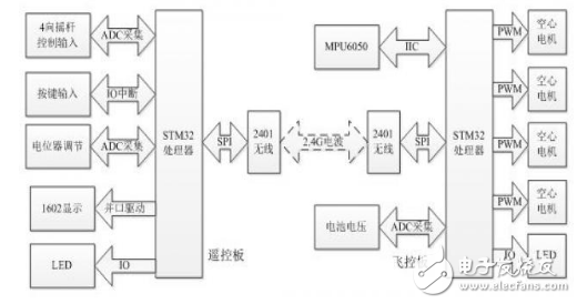
Design and Implementation of Simple Four-Axis Aircraft System Based on STM32
The EI 28 Transformer is a specific type of transformer featuring an EI-laminated core structure, commonly used across various industries including power, electronics, instrumentation, lighting, and audio.
Basic Information
Model: EI 28
Type: Single-phase transformer with an EI-type iron core
Cooling Method: Dry-type transformer
Winding Configuration: Multi-winding transformer
Certifications: May include international standard certifications such as ISO 9001
Product Features
High Efficiency: The EI 28 Transformer is often designed for high efficiency, thanks to optimized designs and materials used. Some manufacturers employ cold-rolled grain-oriented silicon steel strips for the core, which reduces losses and enhances efficiency.
Low Losses: Compared to traditional transformers, the EI 28 Transformer exhibits lower losses, contributing to energy savings and reduced operating costs.
Low Temperature Rise: During operation, the transformer experiences a low temperature rise, extending its lifespan and improving system stability.
Customization: Many manufacturers offer customization options for the EI 28 Transformer, allowing clients to specify different power ratings, sizes, and appearances based on their unique requirements.