FRP Duct Rodder,Fiberglass Duct Rodder,Frp Duct Rodder Snake,Snake Duct Rodder Hebei Dingshengda Composite Material Co., Ltd. , https://www.frpdsd.com
Synchronous rectification buck circuit principle
Synchronous rectification is an advanced technique that replaces traditional diodes with power MOSFETs, which have very low on-resistance. This significantly reduces conduction losses during the rectification process, leading to a substantial improvement in the efficiency of DC/DC converters. Unlike conventional diodes, this method eliminates the voltage drop caused by the Schottky barrier, making it ideal for high-efficiency power conversion systems.
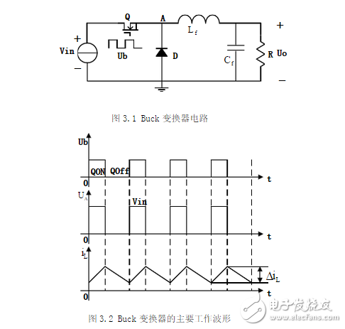
The Buck circuit consists of a power transistor switch Q connected in series with the load. The operation of the circuit is controlled by a periodic driving signal, ub, which turns the transistor on and off. When the transistor is on, assuming negligible saturation voltage, the output voltage uo equals the input voltage. When the transistor is off, and if we neglect leakage current, the output voltage drops to zero. The main working waveforms are illustrated in Figure 3.2.
**Synchronous rectification buck circuit principle**
The schematic of the synchronous rectification Buck circuit is shown below:
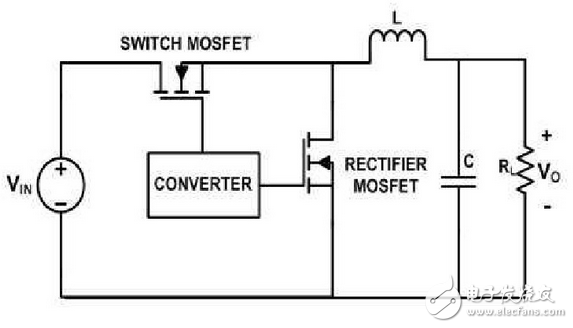
By replacing the diode with a power MOSFET, the circuit achieves higher efficiency and lower power loss. The average output voltage of a Buck converter is always less than the input voltage, as it steps down the voltage level.
When the inductor current does not drop to zero during each cycle, the converter operates in continuous conduction mode (CCM). This ensures smooth current flow and better regulation.
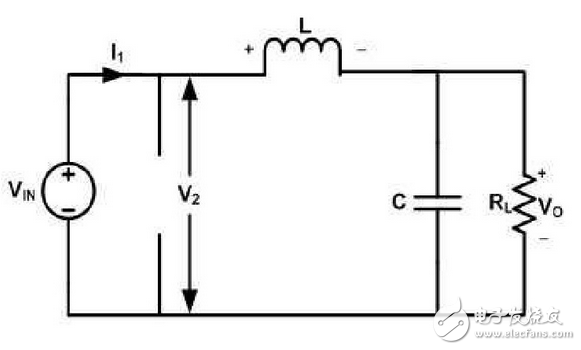
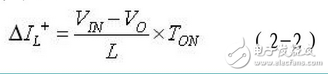
During the on-time, the inductor is charged, and the voltage across it is Vin - Vo. The current increases linearly according to the equation:
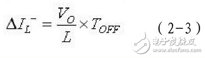
When the switch is turned off, the inductor discharges through the MOSFET, reversing the voltage across it. The current decreases linearly as described by:
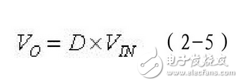
Over one switching cycle, the increase and decrease in inductor current must be equal. This leads to the well-known relationship between the input and output voltages:
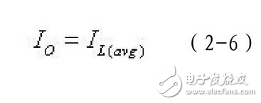
Throughout the cycle, the inductor transfers energy to the filter capacitor and load. Since the capacitor has zero average current per cycle, the output current is essentially the average inductor current:
The waveform of the converter operating in continuous conduction mode is shown below:

This detailed explanation highlights how synchronous rectification improves efficiency, reduces losses, and enhances performance in DC/DC conversion systems.