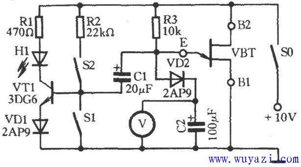
This is a circuit diagram for testing the performance of a single-junction transistor. As shown in the figure, the measured single-junction transistor VBT (model: BT33) and resistors R3 and capacitor C2 form a relaxation oscillator. When VBT is activated, transistor VT1 receives a bias current through resistor R2 (with S1 open and S2 closed), causing the light-emitting diode H1 to light up. The 10V power supply charges capacitor C2 through resistor R3 and diode VD2. The voltmeter V can monitor the voltage across C2, which gradually increases over time. Once the voltage at the E terminal reaches the peak voltage of VBT, the E-B1 junction of VBT turns on automatically. This allows the voltage stored in capacitor C1 to discharge through the E-B1 junction, reverse-biasing the emitter junction of VT1 and turning off H1. If the tested single-junction transistor VBT is functioning properly, capacitor C1 will repeatedly charge and discharge, causing H1 to flash alternately. If H1 remains lit continuously, it may indicate that the B1 and B2 pins of VBT are reversed. In this case, you can swap the B1 and B2 pins of VBT (which also helps in correctly identifying the pinout). If the problem persists, the transistor is likely defective. Dj Speaker,Portable Bluetooth Speaker,Lf600 Multifunctional Speaker,Speakers For Large Events NINGBO RFUN AUDIO TECHNOLOGY CO.,LTD , https://www.mosensound.com