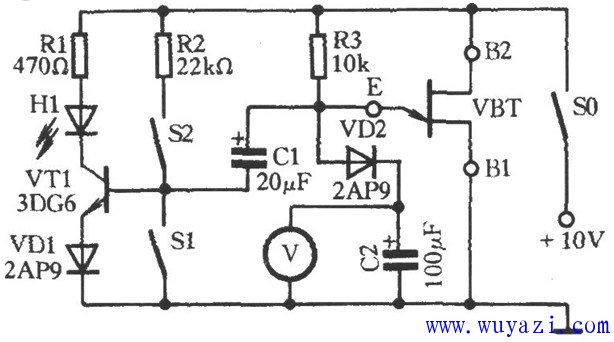
This is a schematic diagram of a single-junction transistor performance test circuit. As shown in the figure, the tested single-junction transistor VBT (model: BT33) and components R3 and C2 form a relaxation oscillator. When the VBT is activated, the transistor VT1 receives a bias current through the bias resistor R2 (S1 is open and S2 is closed), causing the light-emitting diode H1 to illuminate. The 10V power supply charges capacitor C2 through resistor R3 via diode VD2. The voltmeter V can monitor the voltage across C2, which gradually increases over time. Once the voltage at the E terminal reaches the peak voltage of the VBT, the E-B1 junction of the VBT turns on automatically. This allows the voltage stored in capacitor C1 to discharge through the E-B1 junction, reverse-biasing the emitter junction of transistor VT1, and causing H1 to turn off. If the tested single-junction transistor VBT is functioning properly, capacitor C1 will repeatedly charge and discharge, resulting in H1 flashing alternately. However, if H1 remains on continuously, it may indicate that the B1 and B2 terminals of the VBT are incorrectly connected. In such cases, you can swap the B1 and B2 pins of the VBT (which also helps in correctly identifying the pinout). If the issue persists after swapping, the single-junction transistor is likely defective. This simple yet effective test circuit is commonly used for diagnosing single-junction transistors. It provides a visual and measurable way to determine whether the transistor is working as expected. By observing the behavior of the LED and the charging/discharging pattern of the capacitors, you can quickly assess the condition of the device. This method is especially useful for hobbyists and electronics enthusiasts who need an easy way to test components without complex equipment. Midrange Speakers Car Audio,Midbass Speaker,Shopping Mall Conference Speakers,High Performance Broadcast Loudspeaker NINGBO RFUN AUDIO TECHNOLOGY CO.,LTD , https://www.mosensound.com