DSD Composite offers wildly range of Ladder Type Cable Trays made of FRP (Fiberglass Reinforced Plastic). These FRP Cable Trays are used for installation of power cables and control cables. It is manufactured using highest quality of FRP pultruded material, which is extremely durable and resistant to various chemicals environments. Ladder Type FRP cable trays are suitable for the laying of larger diameter cables, this type of FRP cable trays has the characteristics of lightweight, low cost, heat dissipation, good air permeability. FRP Cable Tray,frp tray,channel cable tray,grp cable tray,frp ladder tray Hebei Dingshengda Composite Material Co., Ltd. , https://www.frpdsd.com
Synchronous rectification buck circuit principle
Synchronous rectification is an advanced technique that replaces traditional diodes with power MOSFETs, which have significantly lower on-resistance. This substitution reduces conduction losses during the rectification process, thereby greatly enhancing the efficiency of DC/DC converters. Unlike conventional diodes, MOSFETs do not introduce a dead zone voltage due to the Schottky barrier, making them ideal for high-efficiency power conversion systems.
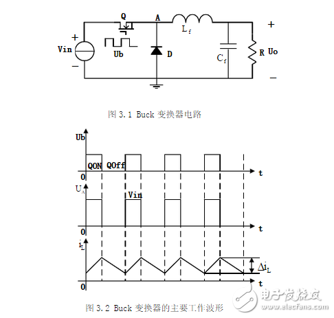
The basic structure of a Buck converter includes a power transistor switch, Q, connected in series with the load. The circuit is illustrated in Figure 3.1. A periodic driving signal, ub, controls the switching of the transistor Q. When the transistor is turned on, and assuming negligible saturation voltage drop, the output voltage uo equals the input voltage. Conversely, when the transistor is off, and ignoring any leakage current, the output voltage drops to zero. The main operating waveforms of this circuit are shown in Figure 3.2.
**Synchronous Rectification Buck Circuit Principle**
The schematic of the synchronous rectification Buck circuit is shown below:
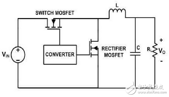
In this configuration, replacing the rectifier diode with a power MOSFET improves the overall efficiency of the converter by minimizing forward voltage drop and conduction losses.
The average output voltage of a Buck converter is always less than the input voltage, as it steps down the voltage level. The operation of the converter can be categorized into two modes: continuous conduction mode (CCM) and discontinuous conduction mode (DCM). In CCM, the inductor current never reaches zero during each switching cycle, ensuring a smooth and stable output.
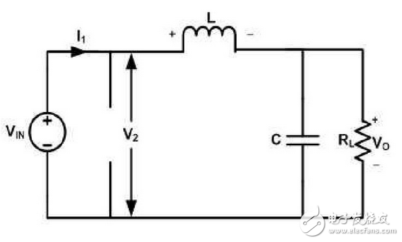
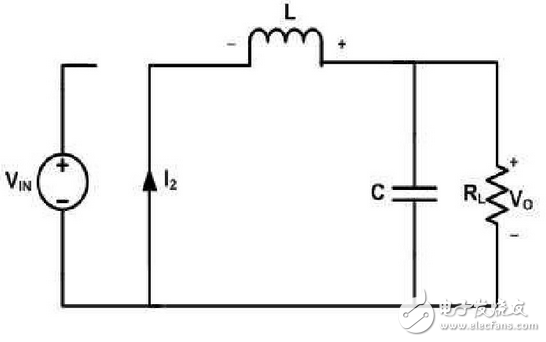
**Equivalent Circuit Diagram When the Converter Switch is Turned On**
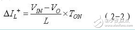
During the on-state, the inductor is connected between the input voltage (Vin) and the output voltage (Vo). The relationship between these voltages is given by:
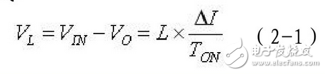
At this stage, the inductor current increases linearly, storing energy in the magnetic field. The rate of change of the inductor current is described by:
**Equivalent Circuit Diagram When the Converter Switch is Turned Off**
When the switch is turned off, the polarity of the inductor voltage reverses, causing the current to decrease linearly. The equation governing this phase is:
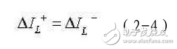
The increase in current during the on-time must equal the decrease during the off-time over one full switching cycle:
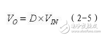
From this, the relationship between the output voltage and the input voltage can be derived as:
Throughout the switching cycle, the inductor delivers energy to the filter capacitor and the load. Since the filter capacitor has zero average current per cycle, its stored energy remains constant. As a result, the output load current equals the average inductor current:
**Waveform of the Converter Operating in Continuous Conduction Mode**
The waveform for the converter operating in CCM is illustrated below:

This waveform shows the continuous flow of inductor current, demonstrating the stable and efficient operation of the synchronous rectification Buck converter.