Realization of Hanxian for ultra-thin display OLED
With the development of science and technology, electronic display technology is also constantly updated. From the traditional cathode ray tube (CRT) to the advanced liquid crystal display (LCD). Now being transitioned to the third generation display technology, candidates for the third generation display technology include plasma discharge display (PDP), organic electroluminescent screen (OLED), light emitting diode (LED), and field emission display (FED) Wait. At present, the most fiercely competitive in research and development are PDP, OLED, LCD. They have their own strengths, but the ultimate goal they pursue is the same, which is to achieve light weight, thin body, high brightness, fast response, high definition, low voltage, high efficiency, long life and low cost. This article gives a brief introduction to OLED, currently recognized as the most ideal display technology, and gives a hardware configuration and software design method for OLED display to display Chinese characters.
Introduction and characteristics of OLED
When some electrodes made of special strong fluorescent organic materials are coated with appropriate electrodes on both surfaces and voltage is applied, the film will emit light. This process is called Organic Electroluminescence (Organic Electroluminescence)
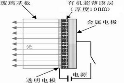
, Referred to as EL), because its light-emitting principle is very close to inorganic light-emitting diodes, so it is also called OLED (Organic Light EmitTIng Diode), is an electrical dimming process. Scientists have discovered this phenomenon as early as the 1930s. However, due to the slower progress in materials and device technology, it has not received much attention from academia and industry. FIG. 1 is a schematic diagram of the basic structure of an OLED device, which includes a substrate, a transparent electrode (anode), an organic layer, and a metal electrode (cathode). Organic electroluminescence display technology (OLED) is striking the mainstream position of LCD in flat panel display with its excellent technical performance, and it is likely to replace it.

Figure 1 The basic structure of an organic electroluminescent device
Therefore, as many as hundreds of scientific research institutions and enterprises in the world have invested huge financial and human resources in the research and development of OLED technology. According to predictions by relevant foreign agencies, in the global image display, the market share of displays using OLED technology will increase rapidly by 2005, reaching nearly 4.5 billion US dollars in sales, including nearly 500 million US dollars for OLED materials, and the development trend It will continue to expand. OLED will be widely used in national defense, home, and various digital instruments and equipment, and as one of the technological levels of a country in the information age, it will occupy a decisive position in the entire national economy and national defense industry.
89C52 connected with OLED
Take the RGS29128064 GH000 organic light-emitting OLED display module produced in Taiwan as an example to introduce its application. The description of the RGS29128064 GH000 electrical interface is as follows:
Among them: GND, VCC ground and + 5V power supply, Vp connects to 7 ~ 12V, the other wiring is connected to the 89C52 port line, and the control instructions are written according to the T6963C drive control module instructions.
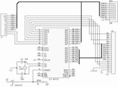
In our common industrial control, all Chinese characters are generally not used, and very few Chinese characters are usually used. We extract it to form a small Chinese character library or Western character library. 89C52 microprocessor has 4K ROM memory, in addition to processing software, it can hold 200 Chinese characters (16 × 16 dot matrix), which can basically meet the requirements of industrial control. Using 89C52 microprocessor to control the RGS29128064GH000, the hardware connection is shown in Figure 2.

Figure 2 89C52 and RGS29128064GH000 hardware connection diagram
J1 is connected to a 2 × 8 keyboard, and J2 is connected to the RGS29128064 GH000 (OLED) display with built-in T6963C drive controller to form a display control module with both a keyboard and a self-made Chinese character library. It is connected through a serial port and takes two or three hours. The control processing of the OLED display screen can be completed, which not only saves the developer's time, but also saves the resources of the single chip microcomputer. The specific method is as follows:
First, using the self-editing library function My.lib generated by Keil C51, the 128 × 64 OLED display is divided into 64 units, as shown in Table 1, the functions include initialization, display of Chinese characters and Western characters, etc. The preparation of these functions Can refer to the built-in T6963C LCD display drive controller.
By modifying the communication parameters in the main function main (), the font encoding in the Western library header file West.h and the Chinese library header file Chinese.h, the font encoding is completed by the modulus taking program. The specific method is as follows:
#include
#include
#include
#include
void main (void)
{
IniTIalOLED (); / Initialize OLED
SCON = 0x50;
TMOD = 0x20;
TH1 = 0xfd;
TL1 = 0xfd;
Receive (); / Receive parameters
}
Chinese.h file
unsigned char code chinese [] = {
/ * 0th word of Chinese font * /
/ *-Text: Tuo-* /
/ *-Song type 12; The corresponding dot matrix under this font is: width x height = 16x16-* /
0x00, 0xFE, 0x12, 0x2A, 0xC6, 0x00, 0x18, 0x08, 0xE8, 0x09, 0x0 E, 0x88, 0x88, 0x18, 0x08, 0x00, 0x00, 0xFF, 0x02, 0x04, 0x03, 0x00, 0x00, 3 , 0x41, 0x41, 0x40, 0x40, 0x78, 0x00, 0x00,}
West.h file
uns
igned char code west [] = {
/ *-Text: A-* /
/ *-Song type 12; The corresponding dot matrix under this font is: width x height = 8x16-* /
/ * The 0th character of the Western font * /
0x00, 0x00, 0xC0, 0x38, 0xE0, 0x00, 0x00, 0x00, 0x20, 0x3C, 0x23, 0x02, 0x02, 0x27, 0x38, 0x20,}
Compile and connect My.lib to generate an executable file, burn and write in 89C52 to form the OLED Hanxian system needed by itself.
The OLED Hanxian system is connected to the main system through a serial port. In the main system, the functions of controlling the display position, displaying Western or Chinese, and reading keyboard data are as follows:
void main (void)
{
SCON = 0x50;
TMOD = 0x20;
TH1 = 0xfd;
TL1 = 0xfd;
send (0, xx, xx); / * clear screen * /
send (1,0x01,0x02); / * Display the second Western language in the Western header file west.h at the first position on the screen * /
send (2,0x02,0x02); / * Display the second Chinese in Chinese header file chinese.h at the second position on the screen * /
send (3,0x01, xx); / * Delete the first line on the screen * /
send (4, xx, xx); / * Read keyboard value * /
}
Through the above hardware connection and the corresponding library functions, the Chinese character display of the OLED display can be easily realized through the serial port, including the display of Chinese characters in any font of 16 × 16 dot matrix; the display of English characters or Arabic numerals in any font of 8 × 16 dot matrix ; Clear screen; clear a line and 2 × 8 keyboard control, etc. Using this function module not only shortens the development cycle of developers, but also saves resources of single chip microcomputers.
High-Frequency PCB Advanced Circuits Specification
A high-frequency PCB can meet your needs when incorporating a special signal requirement into your electronic components and products. It offers a frequency range of 500MHz - 2GHz, making it ideally suited for high-speed designs, as well as radio frequency (RF), microwave and mobile applications. These higher transmission frequencies can also provide the faster signal flow rates that are a necessity in today's increasingly complex electronic switches and other components.
Special materials are required to achieve the high frequency provided by this type of printed circuit board - any changes in the Er value of these materials can affect the impedance of the board. Many PCB designers turn to Rogers dielectric material for its lower dielectric loss, reduced signal loss, lower cost of circuit fabrication and better suitability for fast-turnaround prototyping applications.
Apart from choosing the appropriate PCB material and determining the correct the value of the Er, designers should take parameter such as conductor width and spacing, substrate constant into consideration. These parameters must be exactly specified and implemented with the highest level of process control.
We're a High-Frequency PCB Manufacturer That Takes the Time to Assess Your Needs
PCB Manufacture Capabilities
|
Features
|
Capabilities
|
|
Layers
|
1-36 layers
|
|
Material
|
FR-4, Aluminum, Copper, Polyimide, high frequency (Rogers, PTEE, PI, Teflon), etc.
|
|
PCB Type
|
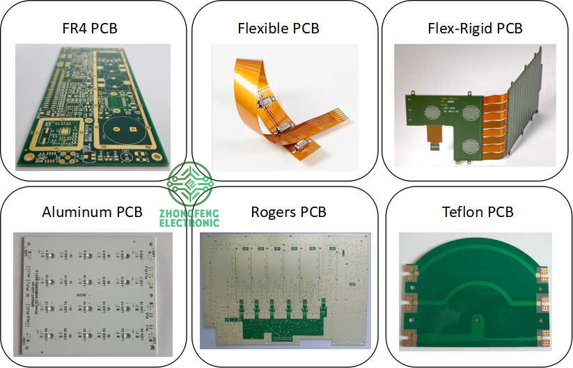
FR-4 Standard PCB, Aluminum PCB , Copper-based PCB, HDI PCB , Rigid-Flex PCB, Flex PCB, Thick Copper PCB and Rogers PCB, etc.
|
|
Board Thickness
|
0.1mm-6.0mm
|
|
Copper Thickness
|
1/2oz-6oz(18um-210um)
|
|
Biggest Board size
|
600mm*1200mm
|
|
Min Tracing/Spacing
|
0.075mm/0.075mm (3mil/3mil)
|
|
Min drilling Hole diameter
|
0.15mm(6mil), 0.1mm(4mil)-laser drill
|
|
Solder Mask
|
Green, Black, White, Red, Yellow, Blue and Purple, etc.
|
|
Silkscreen color
|
White, Blue, Black, Red, Yellow
|
|
Surface finish
|
HASL Lead free, Immersion Gold (ENIG), Immersion Tin, Immersion Silver, OSP, Carbon oil, etc.
|
|
Special Techniques
|
Impedance Control, Gold Fingers, Blind/Buried vias, Peelable solder mask, Half holes, Via-in-Pad and Countersink hole, etc.
|
PCB Products Show

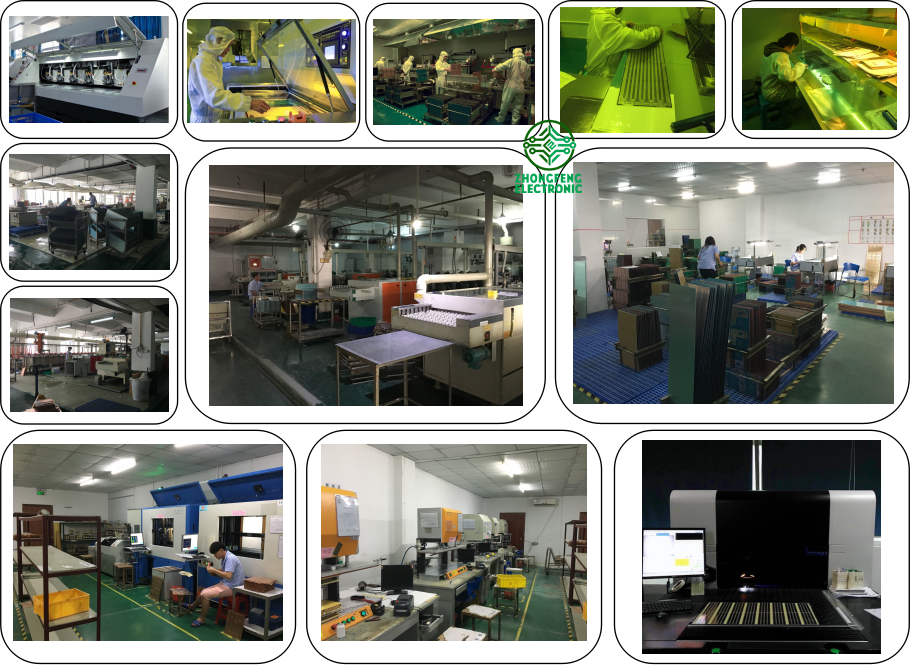
PCB Factory Show

High Frequency PCB
High Frequency PCB,High Frequency PCB Design,High Frequency PCB Materials,High Frequency PCB Board
ZhongFeng Electronic Technology Co., Limited , https://www.dopcba.com


