Deaf hearing aid method with discrete component design 1. Working principle The circuit of a deaf hearing aid is shown in Figure 1. It is essentially a multi-level audio amplifier composed of crystal transistors VT1 ~ VT3. VT1 and the external resistance-capacitance components form a typical resistance-capacitance coupling amplifier circuit, which acts as a pre-amplifier voltage amplifier; VT2 and VT3 form a two-stage direct-coupling power amplifier circuit, in which: VT3 is connected to the emitter output form and its output The impedance is low to match the 8Ω low-impedance earphones. Note: The hearing aids introduced in this article are simple in circuit and easy to obtain materials, suitable for beginners to learn when making, and can also be used for temporary wearing of mildly deaf people. It is recommended that deaf patients go to a special institution to provide hearing aids suitable for their own to avoid small loss !
Reset Lockout
Prevents reset if GFCI is damaged or failed to provide ground fault protection
Tolerate high-torque;power tool installation;and prevents wire pullout
Tamper-Resistant Shutter mechanism
TR GFCI UL,New Version TR GFCI UL,TR Socket GFCI Outlets,New VGersion GFCI with TR Receptacle Hoojet Electric Appliance Co.,Ltd , https://www.hoojetgfci.com
After receiving the sound wave signal, the electret microphone B outputs the corresponding weak electrical signal. The signal is coupled to the base of VT1 through capacitor C1 for amplification. The amplified signal is output from its collector, and then coupled to VT2 through C2 for second-stage amplification. Finally, the signal is output from the emitter of VT3 and sent through jack XS. Play to the earphones.
In the circuit, C4 is a bypass capacitor, whose main function is to bypass various harmonic components that form noise in the output signal to improve the sound quality of the earbud machine. C3 is a filter capacitor, which is mainly used to reduce the AC internal resistance of battery G (actually provides a good path for the audio current of the whole machine), which can effectively prevent the self-oscillation of the circuit when the battery is quickly scrapped, and make the sound of the earbud machine Clearer and louder.
2. Components VT1 and VT2 use 9014 or 3DG8 silicon NPN low-power, low-noise transistors, which require current amplification factor β≥100; VT3 should use 3AX31 and other germanium PNP low-power transistors, and the penetration current Iceo should be as small as possible In some cases, β≥30 is sufficient.
B selects CM-18W (φ10mm × 6.5mm) high-sensitivity electret microphone. Its sensitivity is divided into five blocks, which are represented by color points: red is -66dB, small yellow is -62dB, rhubarb is -58dB, Blue is -54dB, white> -52dB. White dot products should be selected in this production to obtain higher sensitivity. B can also be directly replaced by the blue dot, high sensitivity CRZ2-113F type electret microphone. 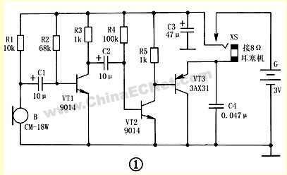
XS selects the two-core jack commonly used in CKX2-3.5 (φ3.5mm caliber) earbud headphones. It needs to be slightly modified before it can be used. Refer to Figure 2 for the restructuring method. Use tweezers to clamp the inner reed of the jack slightly downward, and change the inner and outer reeds from the original normally closed state to the normally open state. The modified jack requires that the inner and outer reeds can be connected reliably after plugging in the headphone plug, and can be reliably separated after the plug is pulled out, so as to double as a power switch. The earphone adopts 8Ω low resistance earplug machine with CSX2-3.5 type (φ3.5mm) two-core plug.
R1 ~ R5 all use RTX-1 / 8W type carbon film resistors. C11 ~ C3 use CD11-10V electrolytic capacitors, C4 use CT1 ceramic dielectric capacitors. G is formed by connecting two No. 5 dry batteries in series, with a voltage of 3V. 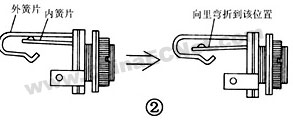
3. Production and use Figure 3 shows the wiring diagram of the printed circuit board of the hearing aid. The actual size of the printed circuit board is about 60mm × 50mm. This printed board does not need to be corroded, as long as the unnecessary copper foil is cut off with a knife. The battery clips can be made of 4 rectangular phosphor copper sheets with a size of about 20mm × 8mm, bent into an “L†shape, punched a small hole in each foot, and riveted directly on the circuit board with copper rivets. 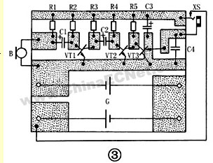
The soldered circuit board is packed in a small plastic or plexiglass box with a size of about 64mm54 × mm × 18mm. In the box panel and the upper side, the sound receiving hole and the mounting hole are opened for the microphone B and the jack XS respectively in advance. The shape of the assembled deaf hearing aid is shown in Figure 4. 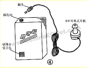
The debugging of this machine is very simple: first, by adjusting the resistance of the resistor R2, the VT1 collector current (DC milliamp meter connected in series with the R3 circuit) is about 1.5mA; then, by adjusting the resistance of R4, the total static of the hearing aid The current (the DC milliamp meter is connected in series with the power supply circuit of the battery G) can be around 10mA. Because the electret microphone B parameters used by each person are different, sometimes the resistance of R1 also needs to be adjusted appropriately, and it should be adjusted until the sound is clearest and loudest.
When in use, the hearing aid is generally placed in the user's jacket pocket, pay attention that the sound receiving hole of the microphone B should face outward. Put on earphones and insert the plug into the jack XS of the hearing aid, the circuit will automatically power on; when the plug is pulled out, the hearing aid will automatically power off and stop working.
Complies with NEC ® requirement, by blocking access to the contacts unless the plug is fully inserted
Only 1.22" Protrusion into Wallbox
Takes up to 20% less space in the wallbox vs. other GFCIs for easier installation
Multi-functional Status Indicator Light
Red and Green LED indications provide simple, intuitive feedback on power, voltage and protection status
Terminals Withstand