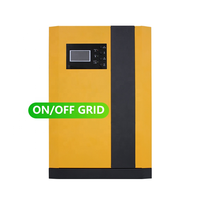
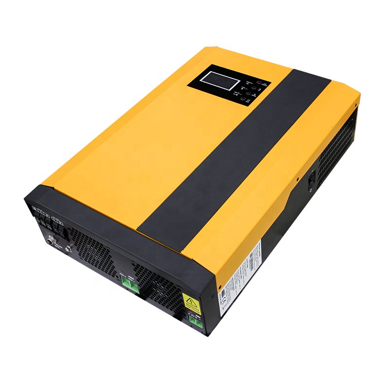
3.5KW-5.5KW MPPT High Frequency Inverter
3.5KW-5.5KW High Frequency Inverter(MPPT)
3.5KW-5.5KW MPPT High Frequency Inverter,Energy Storage System Solar Inverter,Home Off Grid Solar Inverter suzhou whaylan new energy technology co., ltd , https://www.xinlingvideo.com

PCB board common problem detection and solution
Making a PCB board is far more complex than just drilling holes and placing components. While the actual production of a printed circuit board isn’t necessarily difficult, the real challenge comes after the board is completed—debugging. Whether you're an amateur hobbyist or a professional engineer, encountering issues during PCB testing can be frustrating, much like a programmer dealing with a stubborn bug.
Many people find debugging PCBs intriguing, similar to how programmers enjoy solving bugs. Common problems include design flaws, damaged electronic components, short circuits, and poor-quality parts. Some boards may even suffer from breakage or manufacturing defects. These issues can be quite challenging to identify and resolve.
One common problem is a damaged diode or resistor. In such cases, visual inspection often reveals burn marks or physical damage, making it easy to replace the faulty component. However, not all failures are visible at first glance. Components like resistors, capacitors, and transistors may appear intact but still be defective. In these situations, tools like multimeters or capacitance testers become essential for diagnosing the issue.
Sometimes, even after checking all components and finding no obvious faults, the board may still fail to function properly. This is a common frustration for beginners, who might end up rebuilding the board or purchasing a new one. But in many cases, the issue lies in the installation process—components may not be perfectly aligned or may have poor connections, leading to unstable performance.
When instruments fail to detect the problem, engineers rely on their experience to narrow down the fault area. Although they may not always be 100% certain about the exact component causing the issue, replacing suspected parts one by one is often the only way to solve the problem. For example, I once repaired a flooded laptop motherboard and had to replace several components, including a power supply chip, a diode, and a USB charging socket, before finally identifying a shorted component near the south bridge chip through waveform analysis.
In addition to component failures, the PCB itself can be the source of the problem. Issues like broken copper traces due to corrosion or manufacturing defects can cause intermittent or complete failure. In such cases, repairing the board may require soldering thin copper wires to bypass the damaged areas.
PCB troubleshooting is not always straightforward—it requires patience, attention to detail, and a methodical approach. But once the issue is resolved, there's a great sense of satisfaction, much like when a programmer fixes a tricky bug. It’s a rewarding part of the electronics journey, where every problem solved brings a deeper understanding of the craft.