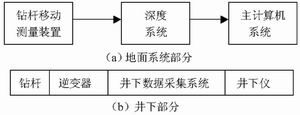
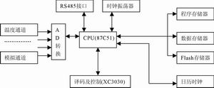
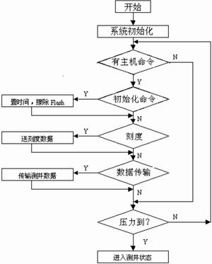
Pick   Important: This paper proposes a low-cost, high-success, cableless horizontal well logging method-drill pipe propulsion cableless logging mode. The hardware and software design of the data storage and transmission module is introduced in detail. introduction With the improvement of the level of petroleum exploration and development, horizontal wells, highly deviated wells, and large displacement wells have become quite common in oilfield development. The logging technology matched with it has also been greatly developed. In the early 1990s , China successfully developed cable wet joint drill pipe propulsion logging technology and drill pipe propulsion protective sleeve logging technology, which basically solved the logging problem of horizontal wells. However, this type of technology is difficult to construct, extremely costly, and has a low logging success rate. The rapid development of communication technology and computer technology, and the continuous improvement of the cost performance of various large-scale integrated circuits, make it possible to use large-scale storage devices. Therefore, according to the special requirements of horizontal well logging, we propose a horizontal well logging method that does not use logging cables __ drill pipe propulsion without cable logging mode. It simplifies the logging technology of horizontal wells and reduces the cost. It has been tested and proved to have a high logging success rate, which solves the problems that need to be solved urgently in the current oilfield development. Cableless logging system The drill pipe propulsion cableless logging system is composed of two parts, surface and downhole ( see Figure 1) . The main function of the ground section is depth-time measurement. It uses the original logging surface equipment to install a drill pipe movement depth-time measurement device to record the depth, speed and corresponding time of the drill pipe in real time and store it in the form of a file. The downhole part includes the original downhole instrument and downhole data acquisition system. Among them, the underground data acquisition system is the core device of the entire system. Its main function is to sample the signal sent by the downhole instrument in an isochronous manner, and record it in a large-capacity storage body in the form of a file, so as to obtain the corresponding relationship between data and time. The working process of the system is as follows: When preparing for logging at the well site, the serial communication method of the host computer of the surface system is used to communicate with the downhole data acquisition system ready to go down through the temporary connection cable. The purpose of the communication is to time the downhole data acquisition, so that the main computer and the downhole Partial clock calibration; set the downhole pressure value of the predetermined sampling depth, start the data acquisition system to start the acquisition, and set the critical value of downhole instrument power supply; at the same time, the downhole instrument is scaled on the ground, and the scale data is input to the host computer through the serial interface . Connect the data acquisition module and the downhole instrument to the drill pipe and push down the hole. The surface system records the relationship between depth and time. When the downhole tool is pushed to a predetermined logging depth, when the pressure detection circuit in the data acquisition module measures that the value is equal to the predetermined pressure value, the inverter power is turned on to measure downhole The well instrument is powered. At this time, the data acquisition module acquires the logging data in an isochronous manner and stores it in the flash memory. This process is until the tool reaches the bottom of the well, and then the depth of stopping the logging is mentioned, that is, the corresponding data of the logging in the two processes of lowering and lifting are recorded in the flash memory, and the inverter power is turned off at this time. When the instrument raises the wellhead, at the surface, the data acquisition module is connected to the host serial port through a temporary cable, and the downhole logging data stored in the flash memory is transmitted to the host. The host computer processes the depth - time data recorded by the surface system and the formation parameter-time data recorded by the downhole system to obtain complete logging data ( ie, formation parameter-depth correspondence data ) . At this time, the entire logging process is completed. In the whole system, the underground data collection, storage and transmission module is the key part. Due to the high temperature, high pressure and high humidity, the environmental conditions are very bad because of thousands of meters downhole. Therefore, in addition to military-grade devices, downhole data acquisition, storage, and transmission modules must also be hot-backed up, using two identical circuits and collecting and recording logging data independently. Ensure a high success rate of logging.      The software and hardware design of the data acquisition, storage and transmission module are given below. Design of data storage and transmission module hardware design The main function of the data storage and transmission module is to collect logging data from downhole instruments at the same time (0.5s) and store the data in the flash memory. After the logging is completed, the module will store the stored logging data through the RS-485 bus. The well data is transmitted to the host, and the communication rate is 300Kbit / s . The storage capacity of flash memory is 10M bytes. In addition, the module can also collect analog quantity such as thermos temperature. Whether the data can be reliably stored and transmitted during the entire logging process is the key to the success of the entire logging. Its structural block diagram is shown in Figure 2 . It is mainly composed of CPU (8751) , program memory, data memory, FLASH memory, clock oscillator, RS-485 interface, A / D converter, decoding and control circuit and calendar clock. The main control chip of this system is the MD87C51 single chip microcomputer, which is responsible for the coordination of the entire module. The main tasks include: RS-485 communication with the host computer and recording the collected data in a large-capacity flash memory. Here , XC3030 from XILINX is used Decoding the address allows the microcontroller to access a large-capacity flash memory. The calendar clock circuit mainly realizes the task of accurate timing, including: receiving the system time issued by the host computer, timing the clock circuit to ensure the time synchronization of the host computer and the circuit; accumulating the time through the timer, and the main control chip MD87C51 Communicate via serial port. The A / D conversion circuit is mainly realized by the AD7824 , which is used to collect the relevant data required by the system and transmit it to the main control module MD87C51 through the microcontroller bus . The realization of large-capacity data storage is to use 20 pieces of AMD flash memory chip AM29F040B ( each piece has a capacity of 512K) . The decoding circuit uses the programmable gate array XC3030 from XILINX . XC3030 is programmed and configured by hardware description language to generate the required address decoding. Since the addressing space of MD87C51 is 64K at most , the method of latching the lower 8 -bit address is used to address the flash memory. The MCU allocates 2K of address space for each flash memory . When the MCU reads and writes the flash memory, it is necessary to first latch the lower 8 bits of the corresponding address into the XC3030 , and then operate the corresponding 2K space. In this way, you can use the ordinary 51 single-chip microcomputer to access large-capacity memory. In this way, you can use the 51 microcontroller to access large address spaces. Picture 1  The construction of drill pipe propulsion cableless logging system  Picture 2  Block diagram of data storage and transmission module Figure 3 Main control microcontroller software flow The calendar clock circuit occupies an important position in the entire cableless logging system, and its timing accuracy directly affects the correspondence between logging data and time. Adopt MD87C51 one- chip computer as the control processor of the calendar clock circuit, accumulate time through the timer interrupt, and communicate with the main control one-chip computer through the serial port at the same time. software design The software design is divided into two parts, the programming of the main control microcontroller and the programming of the microcontroller in the calendar clock circuit.                                                                                        The main control MCU program includes a main program and two interrupt service subroutines. The interrupt service program includes the T0 interrupt service subroutine and the serial port interrupt service subroutine. Among them, the T0 interrupt service program only sets an interrupt flag and does not do any other work; the main task of the serial port interrupt service program is to receive and send data. The main program controls the working state of the entire module. There are two working states of the data storage and transmission module, namely the surface communication state and the downhole logging state. Among them, the surface communication state is to connect the ground to the host and communicate with the host. Including initialization ( erasing flash memory, etc. ) , calibration and data transmission, etc. After entering the downhole logging state, the main job is to collect the logging data of the downhole tool every 0.5s and write it into the flash memory. The main program block diagram is shown in Figure 3 . After power-on reset, the system is initialized first, and then query whether the host computer sends a command to determine the type of command, according to the corresponding initialization command, scale command, data transmission command or pressure reaches the critical value command, set the time, Send calibration data, transmit logging data, or enter logging status. The software of the calendar clock contains a main program and two interrupt service subroutines (T 0 and serial communication ) . The T0 interrupt service routine is mainly to set a flag, the main program accumulates time according to this flag, and the serial communication interrupt service subroutine The main task is to receive commands from the main control microcontroller and send data to the main control microcontroller. After power on, initialize first, check whether there is T0 interrupt after initialization , if there is, then accumulate time, otherwise directly detect whether there is M301 command, if there is, process the command, otherwise continue to detect, the command mainly includes initialization command and transmission Time value command. Conclusion The key of this system is that the surface system and downhole instruments can be synchronized in time, which greatly improves the efficiency and convenience, realizes the cableless horizontal well logging, and solves the problem of high cost of horizontal well logging. This system uses fewer hardware circuits and fewer wires, fully uses the internal resources of programmable logic devices and single-chip microcomputers, meets the functions and requirements required by the system, and improves the reliability, working efficiency, and cost of the circuit. And maintainability are much higher than discrete logic device design patterns. In the system reliability test, the error rate is below 10-9 . Because of the downhole conditions, high-temperature devices must be selected for downhole equipment. Several horizontal wells were measured on the ground, and the ideal results were obtained. At present, this system has been mass-produced in Shengli Oilfield Logging Company. In actual oilfield logging, the work is stable and reliable, and it has been well received by user units. Embedded industrial flat panel display, optional 10.4 "to 19" LCD screens, 50,000 hours long-life LED backlight, support for multiple signal input interfaces, including VGA and Video, special requirements can increase DVI and HMI interfaces; front Panel OSD keys and USB interface are convenient for control and maintenance; support DC 12V power input, special requirements support DC 9 ~ 36V wide voltage input; suitable for harsh work in industrial fields such as factory automation, machinery manufacturing, numerical control equipment, textiles, communication, and power surroundings. Panel Mount Monitor,Touch Screen Mount,Panel Mount Touch Screen,Panel Mount Touch Screen Monitor Shenzhen Hengstar Technology Co., Ltd. , https://www.angeltondal.com