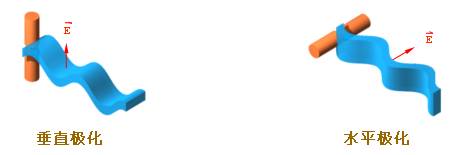
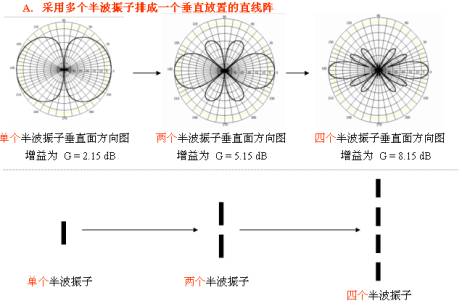
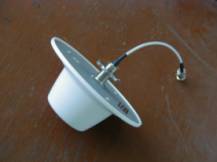
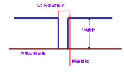
1 antenna 1.1 The role and position of the antenna The power of the radio frequency signal output by the radio transmitter is transmitted to the antenna through the feeder (cable), and the antenna radiates it in the form of electromagnetic waves. After the electromagnetic wave arrives at the receiving location, it is followed by the antenna (receiving only a very small part of the power) and sent to the radio receiver through the feeder. It can be seen that the antenna is an important radio device that emits and receives electromagnetic waves. Without an antenna, there is no radio communication. There are many types of antennas for different frequencies, different uses, different occasions, different requirements, etc. * Radiation of electromagnetic waves When an alternating current flows on the wire, electromagnetic wave radiation can occur, and the ability to radiate is related to the length and shape of the wire. As shown in Figure 1.1 a, if the distance between the two wires is very close, the electric field is bound between the two wires, so the radiation is very weak; open the two wires, as shown in Figure 1.1 b, the electric field is spread in the surrounding space, so Radiation enhancement. 1.2 Symmetrical oscillator Symmetrical oscillator is a classic and most widely used antenna so far. A single half-wave symmetrical oscillator can be used simply and independently or as a feed for a parabolic antenna. Multiple half-wave symmetrical oscillators can also be used to form an antenna array. Oscillators with equal lengths of both arms are called symmetrical oscillators. A vibrator with a quarter-wavelength per arm and a half-wavelength full-length is called a half-wave symmetrical vibrator, see Figure 1.2 a. In addition, there is a special-shaped half-wave symmetrical vibrator, which can be regarded as a full-wave symmetrical vibrator folded into a narrow rectangular frame, and the two end points of the full-wave symmetrical vibrator are overlapped. This narrow long rectangular frame is called Reducing the dipole, note that the length of the dipole is also half the wavelength, so it is called a half-wave dipole, see Figure 1.2b. 1.3 Discussion of antenna directivity 1.3.1 Antenna directivity One of the basic functions of the transmitting antenna is to radiate the energy obtained from the feeder to the surrounding space, and the second basic function is to radiate most of the energy in the desired direction. Vertically placed half-wave symmetrical oscillators have a flat “doughnut†-shaped stereo pattern (Figure 1.3.1 a). Although the three-dimensional pattern is strong in three-dimensional sense, it is difficult to draw. Figures 1.3.1 b and 1.3.1 c show its two main plane patterns, which describe the directivity of the antenna on a specified plane. As can be seen from Figure 1.3.1 b, the radiation is zero in the direction of the axis of the vibrator, and the maximum radiation direction is on the horizontal plane; while from Figure 1.3.1 c, it can be seen that the radiation in the various directions on the horizontal plane is as large. 1.3.2 Enhanced antenna directivity Several symmetrical vibrator arrays can control the radiation and produce a "flat donut", further concentrating the signal in the horizontal direction. The figure below is a stereo directional diagram and a vertical directional diagram when four half-wave symmetrical oscillators are arranged vertically along a vertical line into a vertical quaternion array. You can also use the reflector to control the radiant energy to one side The flat reflector is placed on one side of the array to form a sector-shaped area to cover the antenna. The following horizontal plane diagram illustrates the role of the reflecting surface-the reflecting surface reflects the power in one direction, increasing the gain. Basic knowledge of antenna omnidirectional array (vertical array without plane reflector) 1.3.3 Gain The gain of the half-wave symmetrical oscillator is G = 2.15 dBi; the four half-wave symmetrical oscillators are arranged up and down along the vertical line to form a vertical quaternion array, and the gain is about G = 8.15 dBi (the unit of dBi indicates that the comparison object is isotropic uniform The ideal point source of radiation). If a half-wave symmetrical oscillator is used as a comparison object, the unit of gain is dBd. 1.3.4 Lobe width The pattern usually has two or more lobes. The lobes with the largest radiation intensity are called main lobes, and the remaining lobes are called side lobes or side lobes. See Figure 1.3.4 a. On both sides of the maximum radiation direction of the main lobe, the angle between two points where the radiation intensity is reduced by 3 dB (power density is reduced by half) is defined as the lobe width (also known as the beam width or the main lobe width or half Power angle). The narrower the lobe width, the better the directivity, the farther the distance, and the stronger the anti-interference ability. 1.3.5 Front to back ratio In the direction diagram, the ratio of the maximum value of the front and back lobes is called the front-to-back ratio, and is denoted as F / B. The larger the front-to-back ratio, the smaller the backward radiation (or reception) of the antenna. The calculation of the ratio F / B before and after is very simple ------- 1.3.6 Some approximate calculation formulas of antenna gain 1) The narrower the antenna main lobe width, the higher the gain. For general antennas, the gain can be estimated using the following formula: G (dBi) = 10 Lg {32000 / (2θ3dB, E × 2θ3dB, H)} In the formula, 2θ3dB, E and 2θ3dB, H are the lobe width of the antenna on the two principal planes; 2) For a parabolic antenna, the gain can be approximated by the following formula: G (dB i) = 10 Lg {4.5 × (D / λ0) 2} In the formula, D is the diameter of the paraboloid; λ0 is the central working wavelength; 4.5 is the statistical empirical data. 3) For the upright omnidirectional antenna, there is an approximate calculation formula G (dBi) = 10 Lg {2 L / λ0} In the formula, L is the antenna length; λ0 is the central working wavelength; 1.3.7 Upper sidelobe suppression For base station antennas, people often require that the first side lobe above the main lobe is as weak as possible in the vertical plane (ie, pitch plane) pattern. This is called upper side lobe suppression. The base station serves the mobile phone users on the ground, and the radiation pointing to the sky is meaningless. 1.3.8 Downtilt of the antenna In order to make the main lobe point to the ground, the antenna needs to be tilted down properly. 1.4 Polarization of the antenna The antenna radiates electromagnetic waves into the surrounding space. Electromagnetic waves are composed of electric and magnetic fields. People stipulate that the direction of the electric field is the antenna polarization direction. The commonly used antenna is single-polarized. The figure below shows two basic cases of single polarization: vertical polarization is the most commonly used; horizontal polarization is also used. 1.4.1 Dual-polarized antenna The following figure shows two single-polarized antennas installed together to form a dual-polarized antenna. Note that the dual-polarized antenna has two connectors. The dual-polarized antenna radiates (or receives) two 1.4.2 Polarization loss When the polarization direction of the receiving antenna is completely orthogonal to the polarization direction of the incoming wave, for example, use a horizontally polarized receiving antenna to receive vertically polarized incoming waves, or use a right-handed circularly polarized receiving antenna to receive left-handed circularly polarized When an incoming wave arrives, the antenna cannot receive the incoming wave energy at all. In this case, the polarization loss is the largest, and the polarization is said to be completely isolated. 1.4.3 Polarization isolation There is no perfect isolation of ideal polarization. The signal fed to one polarized antenna will always appear a little bit in another polarized antenna. For example, in the dual-polarized antenna shown in the figure below, suppose that the power input to the vertically polarized antenna is 10W, and as a result, the output power measured at the output end of the horizontally polarized antenna is 10mW. 1.5 Input impedance of the antenna Zin Definition: The ratio of the signal voltage to the signal current at the input of the antenna is called the input impedance of the antenna. The input impedance has a resistance component Rin and a reactance component Xin, that is, Zin = Rin + j Xin. The presence of the reactive component will reduce the antenna's extraction of signal power from the feeder. Therefore, the reactive component must be as low as possible, that is, the input impedance of the antenna should be as pure as possible. In fact, even an antenna that is well designed and debugged always contains a small reactance component in its input impedance. By the way, the input impedance of a half-wave oscillator is four times that of a half-wave symmetric oscillator, ie Zin = 280 (Euro), (nominal 300 Euro). 1.6 Operating frequency range of antenna (band width) One is: under the condition that the standing wave ratio SWR ≤ 1.5, the working frequency bandwidth of the antenna; One is: the bandwidth of the antenna within a range of 3 dB. In a mobile communication system, it is usually defined according to the former one. Specifically, the bandwidth of the antenna is the working frequency range of the antenna when the SWR of the antenna does not exceed 1.5. 1.7 Base station antennas, repeater antennas and indoor antennas commonly used in mobile communications 1.7.1 Basic knowledge of plate antenna Whether it is GSM or CDMA, the plate antenna is the most commonly used type of extremely important base station antenna. The advantages of this kind of antenna are: high gain, good sector pattern, small rear lobe, vertical plane pattern depression angle control, reliable sealing performance and long service life. The plate antenna is also often used as the user antenna of the repeater. According to the size of the sector area, the corresponding antenna model should be selected. 1.7.1 a Example of basic technical indicators for base station panel antennas 1.7.1 b Formation of high gain of plate antenna B. Add a reflector on one side of the linear array (take the vertical array of two-half wave elements with reflector as an example) C. In order to increase the gain of the plate antenna, eight half-wave dipole arrays can be further used It has been pointed out earlier that the gain of four half-wave dipoles arranged in a vertical linear array is about 8 dB; the quaternary linear array with a reflector on one side, that is, the conventional plate antenna, the gain is about 14 ~ 17 dB. 1.7.2 High 2 high gain grid parabolic antenna Starting from the performance-price ratio, people often choose the grid-shaped parabolic antenna as the donor antenna of the repeater. Due to the good focusing effect of the parabola, the parabolic antenna has a strong collecting ability, and the grating parabolic antenna with a diameter of 1.5 m has a gain of G = 20 dB in the 900 megaband. It is particularly suitable for point-to-point communication, such as It is often selected as the donor antenna for repeaters. The parabolic surface adopts a grid structure, one is to reduce the weight of the antenna, and the other is to reduce the resistance of the wind. Parabolic antennas can generally give a front-to-rear ratio of not less than 30 dB, which is exactly the technical index that the repeater system must meet for the receiving antenna to prevent self-excitation. 1.7.3 Yagi Directional 3 Yagi Directional Antenna Yagi directional antenna has the advantages of higher gain, lighter structure, convenient installation and cheaper price. Therefore, it is particularly suitable for point-to-point communication, for example, it is the preferred antenna type for outdoor receiving antennas of indoor distribution systems. The greater the number of Yagi directional antennas, the higher the gain. Generally, 6 to 12 units of Yagi directional antennas are used, and the gain can reach 10 to 15 dB. 1.7.4 Room 4 indoor ceiling antenna The indoor ceiling antenna must have the advantages of light structure, beautiful appearance, and easy installation. The indoor ceiling antennas seen on the market today have many shapes and colors, but the purchase and manufacture of their inner cores are almost the same. The internal structure of this ceiling antenna, although small in size, is based on the antenna broadband theory, with the aid of computer-aided design, and the use of a network analyzer for debugging, so it can well meet the needs of a very wide range of work For the standing wave ratio in the frequency band, according to national standards, the antenna operating in a wide frequency band has a standing wave ratio index of VSWR ≤ 2. Of course, it is better to achieve VSWR ≤ 1.5. By the way, indoor ceiling antennas are low-gain antennas, generally G = 2 dB. 1.7.5 Indoor wall 5 Indoor wall-mounted antenna Indoor wall-mounted antennas must also have the advantages of light structure, beautiful appearance, and easy installation. The indoor ceiling antennas seen on the market today have many shapes and colors, but the purchase and manufacture of their inner cores are almost the same. The internal structure of this wall-mounted antenna belongs to an air dielectric microstrip antenna. Because the auxiliary structure of widening the antenna bandwidth is adopted, with the aid of computer-aided design, and debugging using a network analyzer, it can better meet the requirements of working wide frequency band. By the way, the indoor wall-mounted antenna has a certain gain, about G = 7 dB. 2 Several basic concepts of radio wave propagation The frequency bands currently used for GSM and CDMA mobile communications are: GSM: 890 ~ ​​960 MHz, 1710 ~ 1880 MHz CDMA: 806 ~ 896 MHz The frequency range from 806 to 960 MHz belongs to the ultrashort wave range; the frequency range from 1710 to 1880 MHz belongs to the microwave range. If the frequency of the radio wave is different, or the wavelength is different, its propagation characteristics are not exactly the same, or even very different. 2.1 Free space communication distance equation Suppose the transmission power is PT, the transmission antenna gain is GT, and the operating frequency is f. The reception power is PR, the reception antenna gain is GR, and the distance between the receiving and transmitting antennas is R. Then, when there is no environmental interference, the electric wave loss during propagation L0 has the following expression: L0 (dB) = 10 Lg (PT / PR) [Example] Let: PT = 10 W = 40dBmw; GR = GT = 7 (dBi); f = 1910MHz Q: When R = 500 m, PR =? (2) Calculation of PR By the way, when a 1.9GHz radio wave penetrates a brick wall, it loses approximately (10 ~ 15) dB 2.1 Propagation line-of-sight of ultrashort wave and microwave 2.2 Limit direct viewing distance Ultrashort waves, especially microwaves, have high frequencies and short wavelengths, and their surface waves attenuate quickly, so they cannot rely on surface waves for long-distance propagation. Ultrashort waves, especially microwaves, are mainly propagated by space waves. Simply put, a space wave is a wave that propagates in a linear direction in the spatial range. Obviously, due to the curvature of the earth, there is a limit of the direct view distance Rmax for space wave propagation. The area within the farthest direct viewing distance is conventionally called the lighting area; the area beyond the limit direct viewing distance Rmax is called the shadow area. It goes without saying that when using ultrashort wave and microwave for communication, the receiving point should fall within the maximum direct viewing distance Rmax of the transmitting antenna. Affected by the radius of curvature of the earth, the relationship between the limit direct viewing distance Rmax and the heights of the transmitting antenna and the receiving antenna HT and HR is: Rmax = 3.57 {√HT (m) + √HR (m)} (km) Considering the refraction effect of the atmosphere on radio waves, the limit direct viewing distance should be corrected as 2.3 Propagation characteristics of radio waves on the ground The radio wave directly emitted by the transmitting antenna to the receiving point is called a direct wave; the radio wave emitted by the transmitting antenna directed to the ground and reflected by the ground to reach the receiving point is called a reflected wave. Obviously, the signal at the receiving point should be a combination of direct wave and reflected wave. The synthesis of radio waves will not be simply algebraically added as 1 + 1 = 2, and the synthesis result will vary depending on the difference in the path length between the direct wave and the reflected wave. When the wave path difference is an odd multiple of half a wavelength, the direct wave and reflected wave signals are added together to synthesize the maximum; when the wave path difference is a multiple of a wavelength, the direct wave and reflected wave signals are subtracted and synthesized to the minimum. It can be seen that the presence of ground reflection makes the spatial distribution of signal strength quite complicated. Ri = (4 HT HR) / l, where l is the wavelength. It goes without saying that Ri must be less than the limit direct viewing distance Rmax. 2.4 Multipath propagation of radio waves In the ultra-short wave and microwave bands, radio waves will encounter obstacles (such as buildings, tall buildings or hills, etc.) during the propagation process to reflect the radio waves. Therefore, there are a variety of reflected waves that reach the receiving antenna (broadly speaking, ground reflected waves should also be included), this phenomenon is called multipath propagation. Due to multipath transmission, the spatial distribution of the signal field strength becomes quite complicated, with large fluctuations. In some places, the signal field strength is strengthened, and in some places the signal field strength is weakened. Also due to the influence of multipath transmission, the radio wave The direction of polarization changes. In addition, different obstacles have different reflection capabilities for radio waves. For example, the reinforced concrete building has a stronger ability to reflect ultrashort waves and microwaves than brick walls. We should try our best to overcome the negative impact of the multipath transmission effect. This is precisely the reason why people often adopt space diversity technology or polarization diversity technology in communication networks with high communication quality requirements. 2.5 Diffraction propagation of radio waves When a large obstacle is encountered in the propagation path, the radio wave will propagate forward around the obstacle. This phenomenon is called the diffraction of the radio wave. Ultrashort waves and microwaves have higher frequencies, shorter wavelengths, and weak diffraction capabilities. The signal strength behind the tall buildings is small, forming a so-called "shadow zone." The degree of signal quality is not only related to the height of the building, but also to the distance between the receiving antenna and the building, but also to the frequency. For example, there is a building with a height of 10 meters. At a distance of 200 meters behind the building, the received signal quality is almost unaffected, but at 100 meters, the received signal field strength is significantly weaker than when there is no building. Note that, as mentioned above, the degree of attenuation is also related to the frequency of the signal. For RF signals of 216 to 223 MHz, the received signal field strength is 16 dB lower than when there is no building. For RF signals of 670 MHz, the received signal The field strength is 20dB lower than when there is no building. If the height of the building is increased to 50 meters, the field strength of the received signal will be affected and weakened within 1000 meters from the building. In other words, the higher the frequency, the higher the building, the closer the receiving antenna and the building, the greater the impact on the signal strength and communication quality; on the contrary, the lower the frequency, the shorter the building, the farther the receiving antenna and the building , The smaller the impact. Therefore, when selecting the base station site and setting up the antenna, you must consider the various adverse effects that may be produced by diffraction propagation, and pay attention to various factors that affect the diffraction propagation. 3 Several basic concepts of transmission line The cable connecting the antenna and the output of the transmitter (or the input of the receiver) is called a transmission line or feeder. The main task of the transmission line is to effectively transmit the signal energy. Therefore, it should be able to transmit the signal power from the transmitter to the input of the transmitting antenna with minimum loss, or to transmit the signal received by the antenna to the receiver with minimum loss. At the input, at the same time, it should not pick up or generate spurious interference signals, so that the transmission line must be shielded. By the way, when the physical length of the transmission line is equal to or greater than the wavelength of the transmitted signal, the transmission line is also called a long line. 3.1 Types of transmission lines There are generally two types of ultra-short band transmission lines: parallel two-wire transmission lines and coaxial cable transmission lines; microwave band transmission lines include coaxial cable transmission lines, waveguides and microstrips. The parallel two-wire transmission line is composed of two parallel wires. It is a symmetrical or balanced transmission line. This feeder has a large loss and cannot be used in the UHF band. The two conductors of the coaxial cable transmission line are the core wire and the shielded copper mesh. Because the copper mesh is grounded, the two conductors are asymmetrical to the ground, so they are called asymmetric or unbalanced transmission lines. The coaxial cable has a wide operating frequency range, low loss, and a certain shielding effect on electrostatic coupling, but it is powerless to interfere with the magnetic field. When using it, avoid running in parallel with the line with strong current, nor close to the low-frequency signal line. The ratio of voltage to current on an infinitely long transmission line is defined as the characteristic impedance of the transmission line, expressed as Z0. The formula for calculating the characteristic impedance of a coaxial cable is Z. = [60 / √εr] × Log (D / d) [Europe]. In the formula, D is the inner diameter of the copper network of the outer conductor of the coaxial cable; d is the outer diameter of the coaxial cable core wire; εr is the relative dielectric constant of the insulating medium between conductors. Usually Z0 = 50 ohms, there are also Z0 = 75 ohms. It is not difficult to see from the above formula that the characteristic impedance of the feeder is only related to the conductor diameters D and d and the dielectric constant εr of the medium between the conductors, but not to the length of the feeder, the operating frequency and the load impedance of the feeder terminal. 3.3 Attenuation coefficient of feeder The signal is transmitted in the feeder, in addition to the resistive loss of the conductor, there is also the dielectric loss of the insulating material. These two types of losses increase with the length of the feeder and the operating frequency. Therefore, the layout should be reasonably shortened as much as possible. The magnitude of the loss per unit length is expressed by the attenuation coefficient β, and its unit is dB / m (decibels / meter). Most of the units in the cable technical specification use dB / 100 m (decibels / 100 meters). Suppose the power input to the feeder is P1, and the power output from the feeder of length L (m) is P2, and the transmission loss TL can be expressed as: TL = 10 × Lg (P1 / P2) (dB) The attenuation coefficient is β = TL / L (dB / m) For example, for a NOKIA 7 / 8-inch low-loss cable, the attenuation coefficient at 900MHz is β = 4.1 dB / 100 m, which can also be written as β = 3 dB / 73 m, that is, the signal power at a frequency of 900 MHz, every 73 m When this kind of cable is long, the power is half less. For ordinary non-low-loss cables, for example, SYV-9-50-1, the attenuation coefficient at 900 MHz is β = 20.1 dB / 100 m, which can also be written as β = 3 dB / 15 m, that is, a frequency of 900 MHz Signal power, every time this 15 m long cable is passed, the power will be reduced by half! 3.4 Matching concepts What is matching? Simply put, when the load impedance ZL connected to the feeder terminal is equal to the feeder characteristic impedance Z0, it is said that the feeder terminal is matched and connected. During the matching, only the incident wave transmitted to the terminal load exists on the feeder, and there is no reflected wave generated by the terminal load. Therefore, when the antenna is used as the terminal load, the matching can ensure that the antenna obtains all signal power. As shown in the figure below, when the antenna impedance is 50 ohms, the cable is matched with 50 ohms, and when the antenna impedance is 80 ohms, the cable is not matched with 50 ohms. If the diameter of the antenna element is large, the antenna input impedance changes little with frequency, and it is easy to keep matching with the feeder. At this time, the operating frequency range of the antenna is wider. On the contrary, it is narrower. In actual work, the input impedance of the antenna will also be affected by surrounding objects. In order to make the feeder and the antenna well match, it is necessary to adjust the local structure of the antenna appropriately or install a matching device through measurement when setting up the antenna. 3.55 Reflection loss As mentioned above, when the feeder and the antenna are matched, there is no reflected wave on the feeder, only the incident wave, that is, the feeder transmits only the wave traveling in the direction of the antenna. At this time, the voltage amplitude and current amplitude of the feeder are equal, and the impedance at any point on the feeder is equal to its characteristic impedance. When the antenna and the feeder do not match, that is, when the antenna impedance is not equal to the characteristic impedance of the feeder, the load can only absorb part of the high-frequency energy transmitted on the feeder, but not all of it. Reflected wave. For example, in the figure on the right, because the impedance of the antenna and the feeder are different, one is 75 ohms and the other is 50 ohms, the impedance does not match, the result is 3.6 Voltage standing wave ratio In the case of mismatch, there are both incident and reflected waves on the feeder. Where the phase of the incident wave and the reflected wave are the same, the voltage amplitude is added to the maximum voltage amplitude Vmax to form an antinode; and where the incident wave and the reflected wave are opposite in phase, the voltage amplitude is subtracted to the minimum voltage amplitude Vmin to form a node. The amplitude values ​​of other points are between antinodes and nodes. This synthetic wave is called a traveling standing wave. The ratio of the reflected wave voltage to the incident wave voltage amplitude is called the reflection coefficient, which is denoted as R Reflected wave amplitude (ZLï¼Z00) R = ───── ï¼ â”€â”€â”€â”€â”€â”€â”€ Incident wave amplitude (ZL + Z00) The ratio of the antinode voltage to the nodal voltage amplitude is called the standing wave coefficient, also called the voltage standing wave ratio, which is recorded as VSWR Anti-node voltage amplitude Vmax (1 + R) The closer the terminal load impedance ZL and the characteristic impedance Z0 are, the smaller the reflection coefficient R is, and the closer the standing wave ratio VSWR is to 1, the better the matching. 3.7 Balancing device 3.7.1 Half-wavelength balance converter Also called "U" shaped tube balance converter, it is used for the connection between unbalanced feeder coaxial cable and balanced load half-wave symmetrical vibrator. The "U" tube balance converter also has a 1: 4 impedance transformation. The characteristic impedance of the coaxial cable used in the mobile communication system is usually 50 ohms, so in the YAGI antenna, a folded half-wave vibrator is used to adjust its impedance to about 200 ohms to achieve impedance matching with the main feeder 50 ohm coaxial cable. . 3.7.2 Quarter-wavelength balance-unbalancer The balanced-unbalanced conversion between the balanced input port of the antenna and the unbalanced output port of the coaxial feeder is realized by using the property that the quarter-wavelength short-circuit transmission line terminal is an open circuit at high frequency. Follow WeChat Download Audiophile APP Follow the audiophile class related suggestion 1. The role of the connector The connector, also known as the connector, is mainly used to provide convenient electrical plug-in connection in electronic products and power equipment. It should be widely used ... Interpretation of basic knowledge of notebooks-There are several common discussions about power supply voltage, power supply, power supply and load matching ... Interpretation of the basic knowledge of notebooks-power adapter on power supply voltage, power supply, power supply and load Basic knowledge of electrode materials The internal and external electrodes are an important part of the capacitor. The internal electrode is mainly used to store charge, its effective area size and ... The power amplification (referred to as power amplifier) ​​circuit in the general audio-visual circuit is after the voltage amplifier, the low ... The electret microphone has the characteristics of small size, simple structure, good electro-acoustic performance and low price. It is widely used ... Transformers are used in almost all electronic products. Its principle is simple but according to different ... Basic knowledge of power MOSFET 1. Available on the market Transformers are used in almost all electronic products. Its principle is simple but according to different use occasions (different uses), the winding process of the transformer will ... All communication between computers through the computer network involves transmission ... 1. Long-line transmission line Under high-frequency conditions, electromagnetic waves pass along ... '+ data.data.username +' '; dom + =' Electric Bicycle Battery,24V Ebike Battery Series,24V Cylinder Lithium Battery,Deep Cycle Lithium Battery ZHEJIANG TIANHONG LITHIUM-ION BATTERY CO.,LTD , https://www.tflbattery.com
For many varieties of antennas, proper classification is necessary:
According to usage, it can be divided into communication antenna, TV antenna, radar antenna, etc .; according to working frequency band, it can be divided into short wave antenna, ultra-short wave antenna, microwave antenna, etc .; ; Classification by shape, can be divided into linear antennas, planar antennas, etc .; and so on.
It must be pointed out that when the length L of the wire is much smaller than the wavelength λ, the radiation is very weak; when the length L of the wire is increased to be comparable to the wavelength, the current on the wire will be greatly increased, so that stronger radiation can be formed. 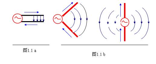


The use of a parabolic reflective surface can make the radiation of the antenna, like the searchlight in optics, concentrate the energy into a small solid angle, thereby obtaining a high gain. It goes without saying that the composition of a parabolic antenna includes two basic elements: a parabolic reflective surface and a radiation source placed on the focal point of the parabolic surface. 
Gain refers to the ratio of the power density of the signal generated by the actual antenna and the ideal radiating element at the same point in space under the condition of equal input power. It quantitatively describes the degree to which an antenna radiates concentrated input power. The gain is obviously closely related to the antenna pattern. The narrower the main lobe of the pattern, the smaller the side lobe and the higher the gain. The physical meaning of gain can be understood in this way-for generating a signal of a certain size at a certain point at a certain distance
If an ideal non-directional point source is used as the transmitting antenna, 100W of input power is required, and when a directional antenna with a gain of G = 13 dB = 20 is used as the transmitting antenna, the input power is only 100/20 = 5W. In other words, The gain of an antenna, in terms of its radiation effect in the direction of maximum radiation, is a multiple of the input power amplification compared to an ideal point source without directionality.
The gain of the half-wave symmetrical oscillator is G = 0 dBd (because it is a ratio of oneself to oneself, the ratio is 1, and the logarithmic value is zero.);
The vertical quaternion array has a gain of approximately G = 8.15 – 2.15 = 6 dBd.
There is also a lobe width, that is, a 10dB lobe width, which, as the name implies, is the angle between two points where the radiation intensity decreases by 10dB (power density drops to one-tenth) in the pattern, see Figure 1.3.4b. 
F / B = 10 Lg {(forward power density) / (backward power density)}
When the front-to-back ratio F / B of the antenna is required, its typical value is (18 ~ 30) dB, and in special cases it is required to reach (35 ~ 40) dB. 
32000 is statistical empirical data. 
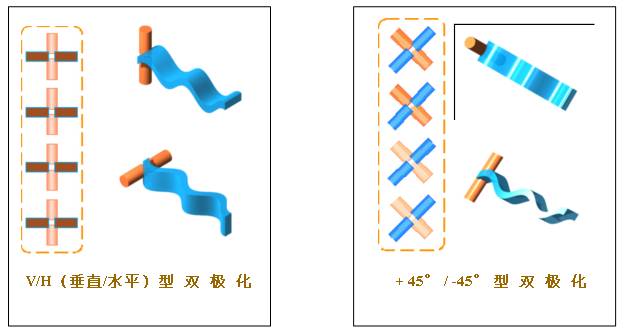
The following figure shows the other two types of single polarization: + 45 ° polarization and -45 ° polarization. They are only used in special occasions. In this way, there are four kinds of single polarization, see the figure below. A combination of vertically polarized and horizontally polarized antennas, or a combination of + 45 ° and -45 ° polarized antennas, constitutes a new antenna --- Dual-polarized antenna 
Vertically polarized waves should be received with antennas with vertical polarization characteristics, and horizontally polarized waves should be received with antennas with horizontal polarization characteristics. Right-handed circularly polarized waves should be received with antennas with right-handed circular polarization, while left-handed circularly polarized waves should be received with antennas with left-handed circular polarization.
When the polarization direction of the incoming wave is different from the polarization direction of the receiving antenna, the received signal will become smaller, that is, polarization loss occurs. For example: when using a + 45 ° polarized antenna to receive vertically polarized or horizontally polarized waves, or when using a vertically polarized antenna to receive + 45 ° or -45 ° polarized waves, etc. To produce polarization loss. If a circularly polarized antenna is used to receive any linearly polarized wave, or if a linearly polarized antenna is used to receive any circularly polarized wave, etc., polarization loss will inevitably occur-only the incoming wave can be received Half energy. 
The input impedance is related to the structure, size, and operating wavelength of the antenna. The half-wave symmetrical oscillator is the most important basic antenna. Its input impedance is Zin = 73.1 + j42.5 (Europe). When the length is shortened by (3 ~ 5)%, the reactance component can be eliminated, and the input impedance of the antenna is pure resistance. At this time, the input impedance is Zin = 73.1 (Euro), (nominal 75 Euro). Note that strictly speaking, the input impedance of a purely resistive antenna is only for the point frequency.
Interestingly, for any antenna, one can always adjust the antenna impedance. Within the required operating frequency range, the imaginary part of the input impedance is very small and the real part is quite close to 50 ohms, so that the input impedance of the antenna is Zin = Rin = 50 ohms-this is necessary for the antenna to be in good impedance matching with the feeder.
Regardless of whether it is a transmitting antenna or a receiving antenna, they always work within a certain frequency range (band width). There are two different definitions of the antenna band width ------
Generally speaking, the antenna performance is different at each frequency point within the operating frequency bandwidth, but the performance degradation caused by this difference is acceptable. 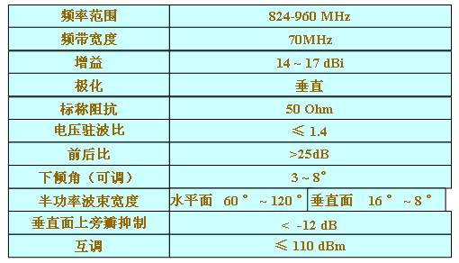

An eight-element linear array with a reflector on one side, that is, an elongated plate antenna, has a gain of about 16 to 19 dB. It goes without saying that the length of the elongated plate antenna is one of the lengths of conventional plate antennas. Times, up to about 2.4 m. 


= 32.45 + 20 Lg f (MHz) + 20 Lg R (km)-GT (dB)-GR (dB)
Answer: (1) Calculation of L0 (dB)
L0 (dB) = 32.45 + 20 Lg 1910 (MHz) + 20 Lg 0.5 (km)-GR (dB)-GT (dB)
PR = PT / (10 7.807) = 10 (W) / (10 7.807) = 1 (μW) / (10 0.807)
= 1 (μW) / 6.412 = 0.156 (μW) = 156 (mμW) # 
Rmax = 4.12 {√HT (m) + √HR (m)} (km)
Since the frequency of electromagnetic waves is much lower than the frequency of light waves, the effective direct viewing distance Re of radio wave propagation is about 70% of the limiting direct viewing distance Rmax, that is, Re = 0.7 Rmax.
For example, HT and HR are 49 m and 1.7 m, respectively, then the effective direct viewing distance is Re = 24 km.
The actual measurement indicates that within a certain distance Ri, the signal strength will fluctuate as the distance or antenna height increases; outside a certain distance Ri, as the distance increases or the antenna height decreases, the signal strength will increase. Monotonous decline. The theoretical calculation gives the relationship between Ri and antenna height HT and HR:
3.2 Characteristic impedance of the transmission line 

VSWR = ───────────── ï¼ â”€â”€â”€â”€
Nodal voltage amplitude Vmin (1-R)
Signal sources or loads or transmission lines can be divided into balanced and unbalanced types according to their relationship to ground.
If the voltage between the two ends of the signal source is equal to the ground and the polarity is opposite, it is called a balanced signal source, otherwise it is called an unbalanced signal source; if the voltage between the two ends of the load and the ground is equal and the polarity is opposite, It is called a balanced load, otherwise it is called an unbalanced load; if the impedance between the two conductors of the transmission line and the ground is the same, it is called a balanced transmission line, otherwise it is an unbalanced transmission line.
A coaxial cable should be used between the unbalanced signal source and the unbalanced load, and a parallel two-wire transmission line should be connected between the balanced signal source and the balanced load, so that the signal power can be effectively transmitted, otherwise their balance or not The balance will be destroyed and will not work properly. If you want to use an unbalanced transmission line to connect with a balanced load, the usual method is to install a "balance-unbalanced" conversion device between the grains, generally called a balanced converter. 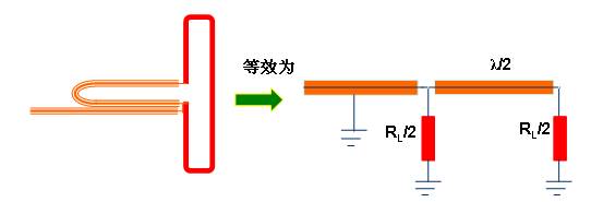


![[Photo] Antenna technology](http://i.bosscdn.com/blog/20/06/41/5211130938.gif)
'+ data.username +'
'+ data.username +'
'; dom + ='
[Photo] Basic knowledge of antenna
Interesting and informative information and technical dry goods
Create your own personal electronic circle
Lock the latest course activities and technical live broadcast
comment
Publish
Share some introductory knowledge of oscilloscope
Published on 2018-03-06 10:39 • 1147 times read
Basic knowledge of connectors
Posted at 2012-06-19 10:36 • 878 views
Interpretation of notebook basic knowledge-power adapter
Posted on 2010-01-23 11:46 • 894 views
Interpretation of notebook basic knowledge-power adapter
Published on 2010-01-18 10:28 • 278 times read
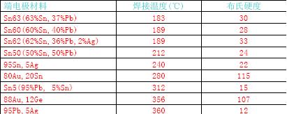
Basic knowledge of electrode materials
Posted on 2009-02-10 12:43 • 477 views
Basic knowledge of power amplifier
Published on 2006-04-17 23:28 • 1379 times read
Basic knowledge of battery
Posted at 2006-04-16 23:46 • 339 views
Basic knowledge of electret microphones
Posted at 2006-04-16 23:46 • 5141 views
Basic knowledge of transformer
Posted at 2006-04-16 23:42 • 282 times read
Basic knowledge of optics related to lamps
Posted at 2006-04-16 23:37 • 604 views
Basic knowledge of power MOSFET
Posted at 2006-04-16 23:34 • 600 views
Basic knowledge of battery
Posted at 2006-04-16 22:45 • 189 times read
Basic knowledge of transformer
Posted at 2006-04-16 22:42 • 187 times read
Basic knowledge of data communication
Posted at 2006-04-16 18:53 • 333 views
[Photo] Antenna technology
Posted at 2006-04-15 21:11 • 244 times read