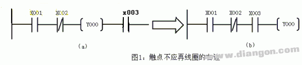
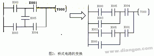
When starting with beginner PLC ladder programming, it's essential to follow certain best practices and develop good habits. Let’s take the Mitsubishi FX series PLC as an example to explain the key rules when creating ladder diagrams. These principles are not only relevant to Mitsubishi but can also be applied to other PLC brands. First, the trapezoidal ladder should always start from the left busbar and end at the right busbar. While the right busbar is often omitted, the left one is usually included. On the left side of each rung, there are a combination of contacts that represent the conditions for driving the logic coil. The coil, which represents the result, should only be connected on the right side of the rung. Contacts should never appear after the coil. For instance, figure (a) should be adjusted to (b): Second, all contacts should be drawn on horizontal lines rather than vertical ones. This helps in clearly defining the logical relationships between components. In the example shown in (a), the relationship between X005 and other contacts isn't clear. To avoid such confusion, all branches should be drawn from left to right and top to bottom, as illustrated in (b). Third, when parallel blocks are connected in series, the more contact points should be placed on the left side of the ladder diagram. Conversely, when series blocks are connected in parallel, multiple contact connections should be placed above the rung. This structure makes the program simpler and reduces scan time, which is especially important in large programs. As shown below: Fourth, double coil output should be avoided. Using the same coil more than once in the same ladder diagram is considered a double coil, which is a common mistake among beginners. In such cases, only the last coil is active, while the previous ones become ineffective. This happens due to the scanning mechanism of the PLC. The PLC CPU operates in a cyclic scan mode, typically consisting of five steps: internal diagnostics, communication with peripherals, input sampling, user program execution, and output refresh. During the input sampling phase, the PLC reads all inputs and stores them in the input image register. Any changes during the program execution phase won’t affect the input image until the next scan cycle. This means the PLC ignores any pulse changes shorter than the scan cycle duration. During the program execution phase, the PLC scans the user program from step 0, performing logical operations sequentially. It uses the input image area data to compute results and writes them to the output image area, not directly to the output terminals. In the output refresh phase, the PLC updates the actual output based on the output image area. This is how the final output is generated. Understanding this process is crucial for avoiding errors like double coil outputs. As shown in the example, if X001 is ON and X002 is OFF, Y003 might turn OFF later because of the sequential execution of the program. This is why using double coils can lead to unexpected behavior. Although double coils are not strictly forbidden, they require careful handling and advanced programming skills. Beginners are advised to avoid them unless absolutely necessary. A common workaround is to use jump instructions to control the execution order. For example, by using a jump instruction, you can ensure that only one coil is activated at a time, preventing conflicts. Another approach is to use auxiliary relays, which allow you to replace double coils with single ones, making the logic clearer and more reliable. By following these guidelines, you can write more efficient and error-free PLC programs. Whether you're working with Mitsubishi or another brand, these fundamental rules will help you build solid programming habits and improve your overall understanding of ladder logic. Our
company offers rubber, and specialty seal and o-ring for molding electronic and electrical Connectors, both circular
and rectangular types. We have in house capabilities and quick turn
around.
Cable Grommets with various Grommet Shapes, Rib Styles, Slot Shapes, Inner Flanges,
and Colors - To have access to our 3D Cable Grommet Design Tool
Silicone Rubber Products,Cable Silicone O-Ring,Rubber Seal,Custom Silicone Seal,Waterproofing O-Ring,Tpe Grommet ETOP WIREHARNESS LIMITED , https://www.etopwireharness.com