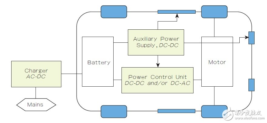
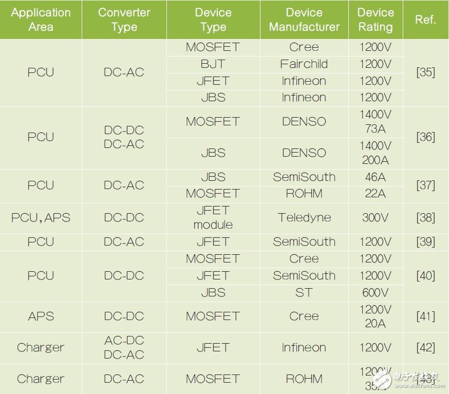
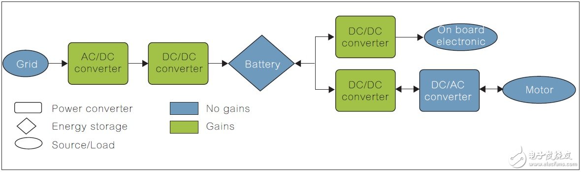
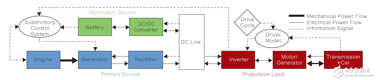
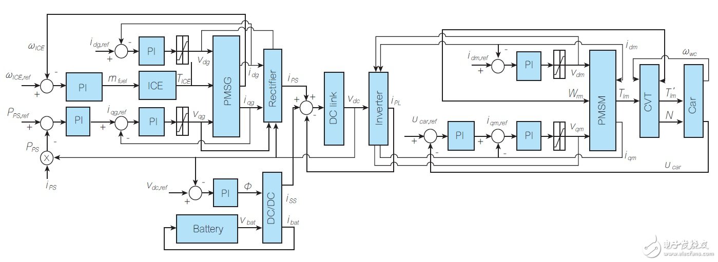
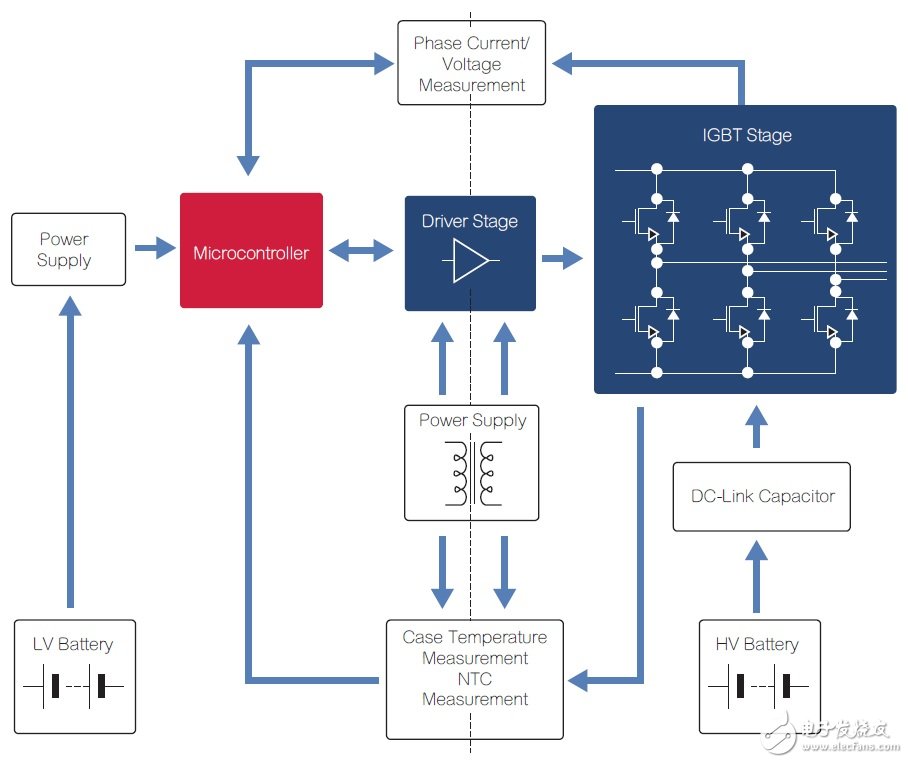
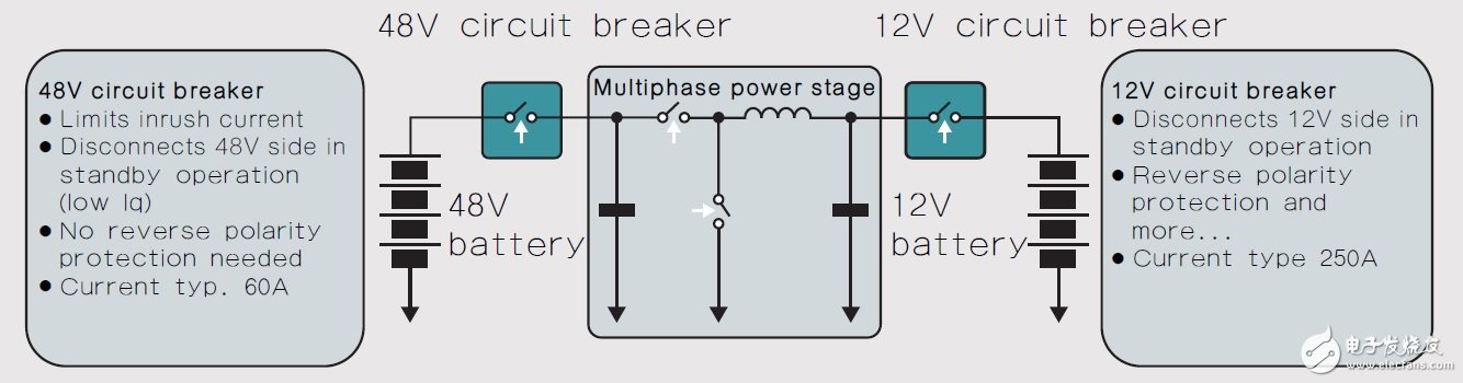
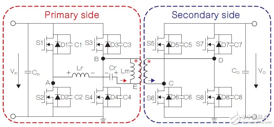
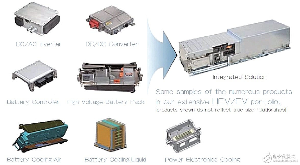
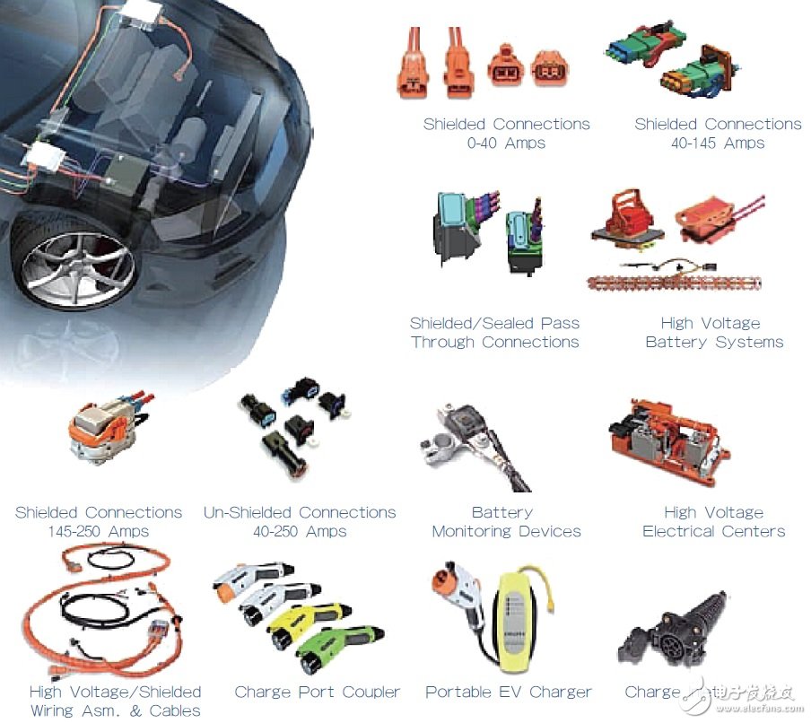
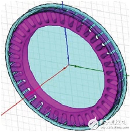
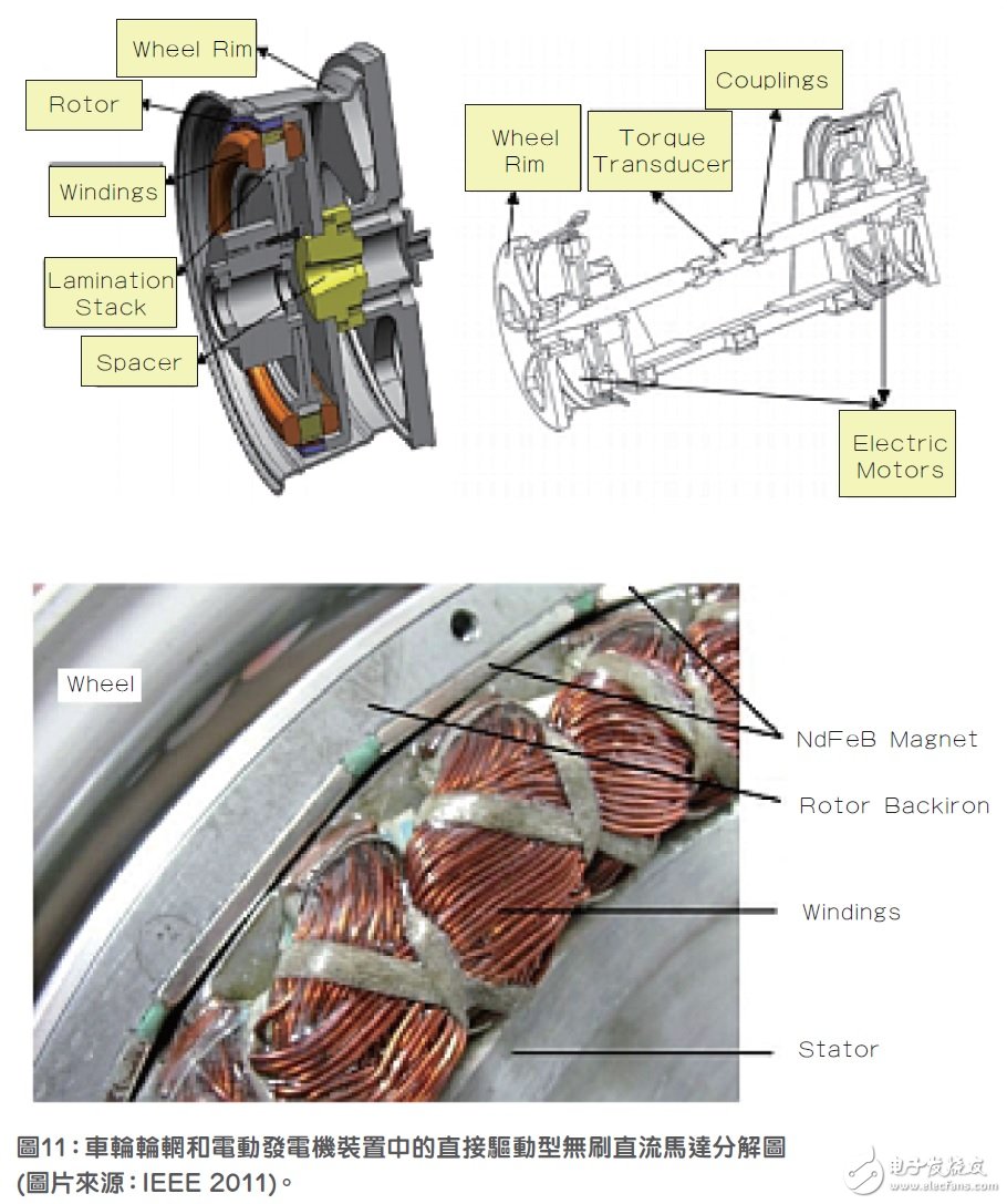
“Save our planet and keep the planet away from pollution!†This is the unanimous voice of scientists and people of insight around the world to reduce greenhouse gas emissions. Cars powered by fossil fuel engines are the culprit. Although there are many alternative technologies to drive cars, the only viable option is electricity. Electric propulsion technology requires the integration of a new architecture of powertrain in the car. This newly added component requires a multidisciplinary study of the corresponding system components. The electric vehicle system consists of an electric motor, a power converter and an energy storage device such as a lithium-ion battery. This new architecture system must be optimized to maximize system efficiency and enable the car to travel the longest on a single charge. Distance, the development of electronic technology has brought important impetus to reduce the emissions of transportation. Electric cars run on batteries, and hybrid cars do the same, but it also uses a fossil fuel-ignited engine as an aid. Energy efficiency is key to achieving success and a bright future for these vehicles, so intelligent power management mechanisms are needed to maximize the efficiency of converting battery energy into wheel mechanical drive, thereby increasing single charge. Driving distance without increasing carbon emissions, ideally, can significantly reduce carbon emissions. The weight, volume and cost of an electric car, as well as the distance traveled by a single charge, are directly related to the efficiency of the power conversion system. SiC power modules are ideal for working in high temperature environments commonly found in automobiles. Let's take a closer look at how SiC power components improve system efficiency. Lighter weight means longer mileage. A typical way to reduce the weight, cost, and size of a power conversion system is to increase the switching frequency of the switching regulator. We all know that when working at higher frequency points, the size and weight of active components such as inductors, capacitors and transformers can be reduced. In this case, the SiC solution is fast. While silicon (Si) power components can operate at high frequencies, SiC has the advantage of being able to handle much higher voltages than Si. SiC is a wide band gap (WBG) semiconductor component, and a wider energy gap means a higher critical electric field (the critical electric field is the blocking voltage in the off state). The high-voltage capability of wide-bandgap SiC components allows them to have lower on-resistance for faster switching speeds and unipolar operation, in part because their carrier frequency needs to be accelerated to higher speeds (higher kinetic energy) ) to overcome a wider energy gap. Although gallium arsenide (GaA) and gallium nitride (GaN) also have high critical electric fields and are an improved component for high power solutions, SiC has other advantages. Such as higher maximum operating temperature, high Debye temperature, high thermal conductivity (in polycrystalline SiC), fast switching in the electric field and high carrier saturation speed with low resistivity, Convenient to produce lower production costs due to silica (SiO2), and high threshold energy results in stronger radiation hardening (radiaTIon hardening). SiC components have many key applications in electric vehicles. Existing electric traction drives are capable of converting 85% of electrical energy into mechanical kinetic energy to drive the wheels. This efficiency is quite high, but SiC can also help increase efficiency. The power converter can benefit from improved efficiency because it delivers battery energy to the engine and can be used in battery charger circuits and any auxiliary power source required (Figure 1). Figure 1 SiC power components have many uses in electric vehicles. Converting a 750V to a 27V SiC power supply for low-voltage electric vehicles is a good example of using SiC power components to increase the efficiency of electric vehicles. This architecture increases efficiency from 88% to a staggering 96%, reduces size and weight by 25%, and eliminates the need for fans to cool excess heat compared to Si solutions. Table 1 shows some important applications for SiC power components for electric vehicles. Table 1 Some SiC applications in the electronic architecture of electric vehicles. (PCU refers to the power control unit; APS refers to the auxiliary power supply) (Table source: 2015 Tenth InternaTIonal Conference on Ecological Vehicles and Renewable Energies) GaN has also contributed to the power improvement of electric vehicles. Insulated gate bipolar transistors (IGBTs), which are widely used in motor drive and DC/DC control, have always been Si-based products. The switching time of these designs is usually on the order of 10k~100kHz, while the switching time of GaN components can reach nanoseconds (ns) and can easily work in a 200°C automotive environment. Like SiC, GaN components can reduce the size of inductors, capacitors, and transformers in power supply architectures due to their higher switching speeds, as well as reduce overall size and weight due to shrinking passive component sizes. We will analyze their efficacy based on the chemical composition of electric vehicle batteries, such as lithium-based chemistry and nickel-hydrogen batteries (NiMH) with high energy density. As described in the previous SiC component section, in order to enable a longer distance for a single charge, it is also desirable to increase the efficiency of the power conversion architecture. The switching speed and minimum on-resistance of Si components have reached their maximum limits, and GaN seems to be a viable solution beyond these limits. Experiments have shown that if the switching frequency can be increased by a factor of five, the volume of the inductor and capacitor can be reduced to one-fifth. Today's GaN technology can support very high speeds. GaN power components perform exceptionally well in four key areas: high temperature operation, higher breakdown voltage, low on-resistance, and nanoscale switching speed for higher operating frequencies. These advantages are similar to GaN and SiC, and they differ in two ways: LEDs and RF transistors have been using GaN; many Si processes are compatible with GaN processes, reducing wafer cost and process cost compared to SiC's higher substrate cost. Since the reliability issue was resolved as early as 2003, today's technology has succeeded in putting the first GaN High Electron Mobility Transistor (HEMT) component into production. These are all normally-on components, so a gate voltage of 0V will be turned on, and any voltage less than 0V will turn off the component. The SiC substrate was used in the early stage, and once the Si substrate can be perfectly combined with GaN, the production cost can be significantly reduced. In 2014, a new cascaded architecture implementation turned the normal conduction component into a normally-off component. Since then, the drive technology has achieved rapid development, integration is getting higher and higher, and power inverters have also made significant progress. GaN components also perform exceptionally well in battery chargers for electric vehicles. These chargers consist of an AC/DC converter plus a DC/DC converter. This combination is a power factor controller (PFC) (Figure 2). Figure 2 Typical electric vehicle power architecture. With GaN and a higher switching speed GaN HEMT, smaller passive components can be realized. The increased frequency directs the power architecture to a lower ripple current through a smaller inductor, thus improving the power factor and resulting in a smaller, lower cost capacitor. Lower chopping currents also have less stress on the capacitor, which increases reliability and longevity. The reliability of GaN has been raised to a very high standard over the past few years, which is the key to the use of GaN in automobiles. Reduce greenhouse gas emissions with hybrid vehicle driveline efficiency About 72% of traffic emissions are currently generated by cars driving on the road. Improving hybrid drivetrain design to increase efficiency is the primary means of reducing emissions. One approach is to enhance the efficiency of the DC-link voltage control architecture, which means that the power converter efficiency of the series hybrid vehicle drivetrain needs to be improved first. The DC-link is usually connected to three drive systems: a primary power supply consisting of a three-phase rectifier; a secondary power supply consisting of a dual active bridge (DAB) DC/DC converter; and a propulsion load consisting of a three-phase inverter (Figure 3) They are related to tandem hybrid vehicles. Figure 3 is a block diagram of the drive train of a hybrid vehicle. In a design topology where the DC-link and battery voltages are not equal, a DC/DC converter intermediate solution is required. An IEEE paper "Voltage Control for Enhanced Power Electronic Efficiency in Series Hybrid Electric Vehicles" describes many methods for studying different architectures and for various methods. DC-link voltage and DC/DC converter control scheme. The pro-porTIonal control law, which is used to control the dynamic DC-link voltage to achieve phase shift between the DAB DC/DC converter bridge gate switching waveforms, will be discussed below. This converter is located between the DC-link of the series hybrid vehicle drive system and the battery, as shown in Figure 4. In this case, the controller makes the DC/DC converter power loss and the loss of the entire drive system lower. Figure 4. Hybrid vehicle driveline interconnection diagram in the control schematic. Engine (ICE), continuously variable transmission (CVT), permanent magnet synchronous motor (PMSG) or hybrid vehicle primary power supply, permanent magnet synchronous motor (PMSM) or hybrid vehicle propulsion load are all systems shown in the figure Key components. In this model, the diesel engine is the main source of power for hybrid vehicles, and the DC battery is the secondary power source. The Management Control System (SCS) controls the proportion of power provided by the two power sources based on battery state of charge (SOC) and motor load. In fact, in this series hybrid vehicle, the DC-link voltage imposes a suppression condition on the ideal working area of ​​the PMSM and PMSG corresponding to the unit modulation index, so that the system can avoid signal distortion and system efficiency. Overshoot status. Keeping the modulation index close to 1 improves the overall efficiency of the power supply circuit in the drive train, maximizing the efficiency of the inverter and rectifier, and the switching process is a major factor in its efficiency loss, so reducing the switching voltage can increase efficiency. This continuous permanent zero voltage switch (ZVS) mechanism that minimizes power loss is best suited for vehicles with high mixing factor (HF), especially in urban environments. The mixing factor is the ratio of installed power from the power supply to the total installed power. This blending factor affects fuel consumption in hybrid vehicles. The main power inverter controls the motor in the electric drive system and is an important device in the hybrid/electric vehicle. The power inverter determines the driving behavior just like the engine management system (EMS) in an engine car. This inverter is suitable for any motor, such as synchronous, asynchronous or brushless motors, and is controlled by an integrated electronic PCB. This PCB is specifically designed by automotive manufacturers to minimize switching losses and maximize thermal efficiency. The other function of the inverter is to capture the energy released by the regenerative brake and feed back the battery. The driving distance of a hybrid/electric vehicle is directly related to the efficiency of the main inverter (Figure 5). Figure 5 Infineon main inverter frame diagram in hybrid/electric vehicles. (Source: Infineon) Managing high-performance batteries in hybrid and electric vehicles requires high-pressure technology. A dual voltage system incorporating 12V and 48V batteries requires bidirectional DC/DC conversion, as shown in Figure 6, to protect the circuit and support architectural functions. Figure 6. A 48V to 12V bidirectional DC/DC converter. In addition, automotive architecture design typically includes a single-phase 3.5kW or 7kW onboard charger module (OBCM) for charging electric vehicles or plug-in hybrid vehicles (PHEVs) from the grid. Conversely, electric vehicles and plug-in hybrid vehicles can be used as energy sources or in smart grids that integrate renewable energy to be used as energy storage equipment. Smart grid operation takes into account the intelligent charging and discharging of electric vehicles and plug-in hybrid vehicles, which is why OBCM must be a two-way DC/DC charger. The best architecture for this design is the boost series resonant bidirectional topology, as shown in Figure 7. It operates above the resonant frequency and features a zero-voltage switching function for maximum power transfer performance at the minimum switching frequency point. This technology replaces the diode rectifier with a MOSFET rectifier compared to a unidirectional power flow converter. This solution also has higher efficiency and wider battery capacity. A major disadvantage of this architecture shown in Figure 7 is that the rectifier bridge has a large loss when turned off, a problem that must be addressed in future designs. Figure 7 Designers sometimes use modulated DAB converters to control simple high-frequency isolation. The advantage of this architecture is the low stress of the components; the main disadvantage is that ZVS cannot be extended to the entire output range, especially under light load conditions. . This figure shows that the boost series resonant bidirectional converter is a better architecture. Delphi integration and cabling Delphi combines all of the meta-components discussed in this article with some other hybrid electric vehicle power electronics components (Figure 8), which is amazing. Figure 8 Delphi achieves a high degree of integration in hybrid/electric vehicles. It is also important to use a suitable internal connector in a hybrid/electric vehicle (Figure 9). Figure 9 The key element of a hybrid/electric vehicle is to minimize quality. Delphi has significant innovations in small-scale cable technology, insulation materials and lighter weight copper alternatives such as aluminum or some special proprietary alloys. (Source: Delphi) "Design and Implement aTI Drive of Electric Drive System for In-Wheel Motor Electric Vehicle Applications", a motor drive system suitable for hybrid and electric vehicles is provided. The Matlab SIMULINK model of the motor-driven hybrid vehicle with computational performance has been developed. Two 14kW DC brushless DC motors are designed and manufactured according to the literature and are mounted in the rim of hybrid vehicle wheels. Figure 10 A brushless DC motor diagram of the rear wheel. In addition, two independently driven rear wheels are also mounted on the Fiat Linea. Electronic control technology replaces the mechanical differential by detecting the angle of the steering wheel. The car's electric drive control system and the electronic control unit (ECU) communicate via the CAN bus, and a successful cascade between the electric drive rear wheel and the ICE-driven front axle. This design chose a brushless DC motor with a concentrated coil because of its low power-to-weight ratio, high efficiency, and ease of control. Figure 11 is an exploded view of a direct drive type brushless DC motor in a wheel rim and a motor generator unit. The power driver for a brushless DC motor consists of an integrated power module (IPM), an 8-bit microcontroller, and an electronic control system. Driver software is developed for IGBT commutation control and pulse width modulation (PWM) voltage control. The system features optocoupler isolation, current and temperature protection, and speed, current, and voltage sensors are embedded in the system. In summary, this article describes some of the developments in recent years in the power management of electric vehicles and hybrid vehicles. In the future, more development results will emerge, and these systems will be further improved to benefit the planet. Hospital Bed Lift,Medical Bed Lift,Hospital Hoyer Lift,Hospital Lifts For Patients XI'AN TYPICAL ELEVATOR CO., LTD , https://www.chinaxiantypical.com