class d amplifier board 200 watt,mono amplifier board,class ab amplifier board,subwoofer plate amplifier Guangzhou Aiwo Audio Technology Co., LTD , https://www.aiwoaudio.com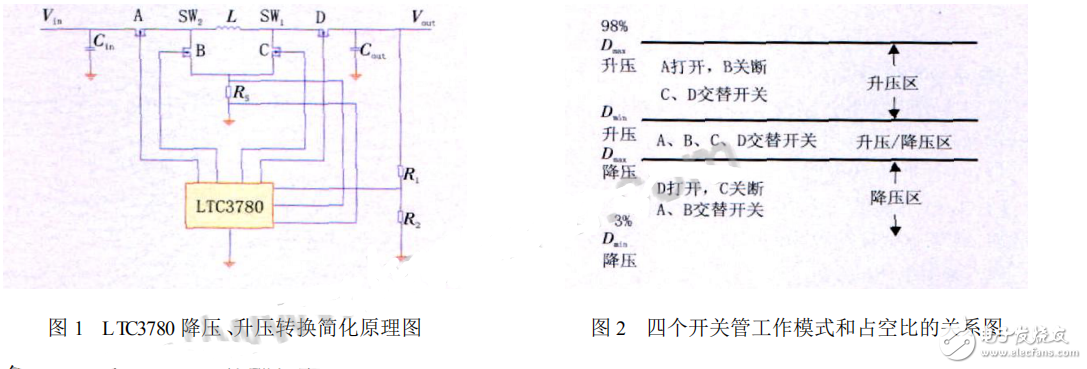
Simulation Analysis of Working Performance of Power Conversion Module LTC3780
The spacecraft's power supply system is relatively straightforward, but in practical applications, different users have varying voltage requirements. To meet these diverse needs, it is often necessary to perform voltage conversion on the power supply. Therefore, designing a power conversion circuit that can handle low-voltage, high-voltage, or standard power supplies is essential for flexibility and adaptability.
Traditionally, achieving an intermediate output voltage over a wide input range has relied on using step-up and step-down transformers or multiple DC/DC converters. This approach, however, leads to complex circuit designs, lower efficiency, and larger physical size. Moreover, conventional voltage conversion systems are typically tailored for specific loads, limiting their ability to support multiple loads effectively. As a result, they often fail to ensure that each load receives its rated power, which restricts their application in more demanding scenarios.
To address these challenges, the LTC3780 power conversion module offers a high-performance solution. It is a versatile boost-buck switching regulator controller capable of operating with input voltages that are lower, higher, or equal to the output voltage. The module allows for setting a maximum output current, simplifying the design while ensuring stable voltage output and high efficiency. Additionally, it supports strong load capacity, making it ideal for various applications.
**Module Introduction**
The LTC3780 features a constant-frequency current-mode architecture that provides a phase-lockable fixed frequency ranging from 200kHz to 400kHz. It operates across a wide input and output voltage range of 4V to 36V, and it ensures seamless switching between boost, buck, and boost/buck modes. The output voltage accuracy is maintained at ±1%, offering reliable performance under varying conditions.
The controller enables continuous mode transitions by controlling four power switches. When the input voltage (Vin) is lower than the output voltage (Vout), the controller operates in boost mode. If Vin is higher than Vout, it switches to buck mode. When Vin is close to Vout, it enters the boost/buck mode. The output voltage is set via an external resistive feedback network connected across the output capacitor. An internal error amplifier compares the feedback signal with a precision reference voltage to maintain stable output.
A simplified schematic of the LTC3780 and its four power switch configuration is shown in Figure 1. The relationship between the working area, the state of the power switches, and the duty cycle (D) is illustrated in Figure 2.
Class D Power Amplifiers: Pioneering Efficiency in Audio Technology
Â
Â