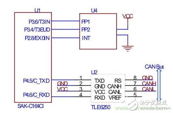
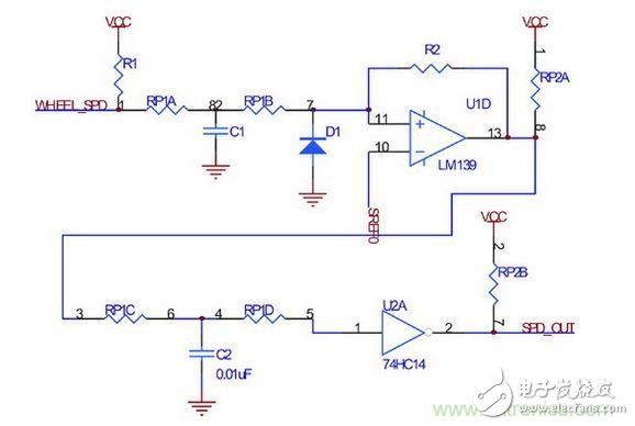
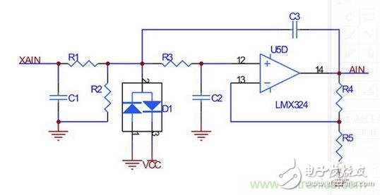
[Introduction] This paper discusses the structural characteristics and signal characteristics of commonly used sensors in ESP systems, and designs the signal processing interfaces of each sensor, including hardware interface circuits and software processing solutions. An integrated module including yaw rate and longitudinal/lateral acceleration sensors is designed to transmit data through the CAN bus and the ECU, which has better anti-interference and reliability. ESP (Electronic Stability Program) is an iconic invention for automotive electronic control. Different R&D institutions have different names for this system, such as Bosch (Cars), which was called Automotive Dynamics Control (VDC) in the early days. Now Bosch and Mercedes-Benz are called ESPs; Toyota is called Car Stabilization. Sex Control System (VSC), Automotive Stability Assist (VSA) or Automotive Electronic Stability Control (ESC); BMW is known as Dynamic Stability Control (DSC). Although the names are not the same, they are based on traditional vehicle dynamics control systems, such as ABS and TCS, which add a lateral stability controller to control the distribution and amplitude of lateral and longitudinal forces in order to control the car in any road condition. Dynamic motion mode, which can improve the dynamic performance of the car under various working conditions. This article describes the circuit analysis of sensors and interface technologies in ESP: Circuit principle Steering wheel angle sensor interface The output of the steering wheel angle sensor is an orthogonal coded pulse. The orthogonally encoded pulse contains two pulse sequences with varying frequencies and a fixed phase offset of a quarter cycle (90°), as shown in Figure 1. By detecting the phase relationship of the two signals, it can be judged as clockwise direction and counterclockwise direction, and according to this, the signal is added/down counted, thereby obtaining the current count cumulative value, that is, the absolute rotation angle of the steering wheel, and the change rate of the rotation angle. That is, the angular velocity can be measured by the signal frequency. In addition, the steering wheel angle sensor has a zero output signal. When the steering wheel is in the middle position, the signal outputs 0V, otherwise it outputs 5V. Through this signal, the absolute rotation angle can be calibrated online. Figure 1 Steering wheel angle sensor pulse sequence waveform The interface circuit of C164CI and steering wheel angle sensor is shown as in Fig. 2. An on-chip incremental coded quadrature decoder is used. The decoder uses two pins of timer 3 (T3IN, T3EUD) as the input of the quadrature pulse. After the relevant register is correctly set, the data register of the timer 3 is The value is proportional to the steering wheel angle, so the angle can be conveniently calculated. The steering wheel angle sensor used in this paper corresponds to 44 pulses per cycle. If the data register of timer 3 is T3, the absolute rotation angle is. Figure 2 Steering wheel angle sensor interface circuit By performing a differential operation, the rate of change of the corner can be obtained. The microcontroller sends the calculated parameters to the ECU via CAN. Wheel speed sensor interface According to the characteristics of the wheel speed sensor signal introduced in the previous section, the design interface circuit is shown in Figure 3. Figure 3 wheel speed sensor interface circuit The circuit uses two levels of filtering and shaping to ensure that the wheel speed signal is not lost at very low speeds, while avoiding signal interference due to suspension vibration. The first stage hysteresis comparison is introduced by resistor R2 and the second stage hysteresis comparison is introduced using 74HC14. Yaw angular velocity, longitudinal/lateral acceleration sensor The installation position of the yaw rate and the longitudinal/lateral acceleration sensor are basically the same, and the output is an analog quantity of 0V-5V. Since the signal fluctuation characteristics caused by the bumps of the car are the same, they are packaged in the same module. The hardware interface is shown in Figure 4, which implements hardware analog pre-filtering to suppress high-frequency noise components in the analog signal from the sensor to prevent aliasing during sampling. Adjusting the parameters of each RC component in Figure 4, you can set the filter cutoff frequency and delay size. During the running of the car, when driving on a better road, because the signal is better, the delay should be as small as possible, and when driving on the bumpy road, the filtering effect is better. However, since the frequency characteristics of the hardware filtering are designed and cannot be modified in real time, it is necessary to design a digital filtering link in the software. Digital filtering commonly used are Wiener filters, Kalman filters, linear predictors, and self-applied filters. Here, the first-order low-pass filtering with small calculation amount and good real-time performance is selected. Figure 4 yaw rate, longitudinal / lateral acceleration sensor interface circuit The managed PoE switch has a simple network management protocol and can be configured by itself. It can filter data addresses, ports, protocol types, services, etc., and usually also has a VLAN division function.
The network-managed PoE switch can provide a comprehensive and intelligent management method to ensure that all network resources are in a good state, so that the stability and security of the network are most effectively guaranteed. In this sense, managed POE Switches are more powerful than unmanaged switches.
1. Large backplane bandwidth and faster data forwarding speed. Gigabit 8 Ports Switch,Managed Switch 8 Port,Managed Poe Ethernet Switches,Gigabit Industrial Ethernet Switch Shenzhen Scodeno Technology Co.,Ltd , https://www.scodenonet.com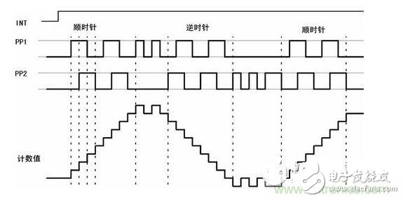
2. The networking is flexible, and the access layer of large and medium networks is applied.
3. The ports provided are flexible, and different interface forms can be selected according to the application of the network
4. Support VLAN division, users can divide areas for different applications, and effectively control and manage the network. Progress suppresses the broadcast storm.
5. The data throughput (Throughput) of the network management switch is large, the packet loss rate (PacketLoss) is small, and the delay (Latency) is low.
6. Data information flow can be controlled based on source, destination, and network segment.