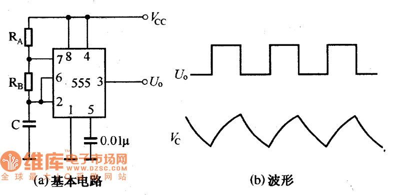
The 555 timer IC is a versatile integrated circuit that can be used to create various types of oscillators and timing circuits. One of its most common applications is the construction of self-excited multivibrators, which generate continuous square wave signals. The basic configuration of such a circuit is illustrated in Figure (a). When the power is first applied, the capacitor C is initially uncharged, so the trigger pin (pin 2) is at a low voltage level. This causes the output (pin 3) to go high.
As the capacitor begins to charge through resistors RA and RB, the voltage across it gradually increases. Once the capacitor voltage reaches 2/3 of the supply voltage (Vcc), the threshold pin (pin 6) triggers the internal comparator, causing the output to switch from high to low. At this point, the capacitor discharges through resistor RB and the internal discharge transistor. When the capacitor voltage drops to 1/3 of Vcc, the output switches back to high, and the cycle repeats, creating a continuous oscillation.
The waveform of the output signal and the capacitor voltage during this process is shown in Figure (b). This kind of oscillator is widely used in electronic projects due to its simplicity, stability, and ease of adjustment. By changing the values of RA, RB, or the capacitor C, you can control the frequency and duty cycle of the output waveform.
Understanding how the 555 timer works in a multivibrator configuration is essential for anyone interested in electronics. It's a fundamental concept that serves as a building block for more complex circuits and designs. Whether you're a hobbyist or an engineer, mastering the 555 timer can open up many possibilities in your projects.
DongGuan BoFan Technology Co.,Ltd. , https://www.ufriendcc.com