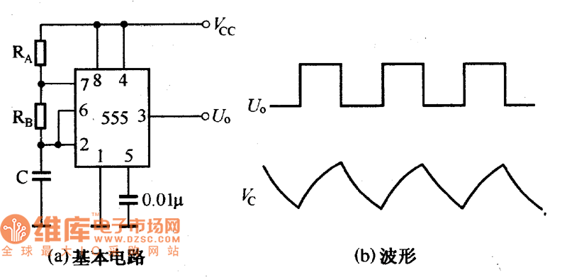
The 555 timer IC is a versatile component that can be used to create various types of self-oscillating circuits, such as multivibrators. One of the most common configurations is the astable multivibrator, which generates continuous square wave outputs without any external trigger. The basic circuit diagram is shown in Figure (a). When power is first applied, the capacitor C is initially uncharged, so the voltage at pin 2 of the 555 timer is low. This causes the output at pin 3 to go high. As the capacitor charges through resistors RA and RB, the voltage across it rises until it reaches 2/3 of Vcc. At this point, the internal comparator triggers, and the output at pin 3 switches to a low level. The capacitor then discharges through resistor RB and the internal discharge transistor. Once the capacitor voltage drops below 1/3 of Vcc, the output switches back to high, and the charging cycle begins again. This continuous charging and discharging process creates a stable oscillation at the output. The waveform of the output voltage and the capacitor voltage is illustrated in Figure (b), showing the characteristic square wave and sawtooth pattern respectively. This type of circuit is widely used in electronics for timing, pulse generation, and frequency control applications. Its simplicity and reliability make the 555 timer one of the most popular integrated circuits in both hobbyist and industrial projects. 555 multivibrator basic circuit related waveform DongGuan BoFan Technology Co.,Ltd. , https://www.ufriendcc.com