Summary Optimization plays a crucial role in the development of C6000 DSP. It can be categorized into system, algorithm, code, and memory optimization based on different aspects. Developers are typically familiar with their own code and often make improvements from the first three areas to enhance overall performance. However, when it comes to memory optimization—especially cache optimization—it becomes more complex because it involves the internal architecture of the chip. The cache maintenance is usually handled automatically by the DSP, leaving little room for user intervention. This makes it seem challenging to start optimizing cache performance. To address these practical issues, TI’s 7.0 series compilers introduced Cache Layout Tools that allow developers to optimize C6000 code efficiently. These tools help improve L1P cache performance significantly. This article provides a detailed guide on how to use them. With the growing popularity of TI DSPs, the C6000 series has become widely used, including models like C64x, C64x+, and C66x. In the development process of C6000 DSPs, it's essential to optimize user programs to fully utilize the computing resources. Optimization can be divided into four main categories: system, algorithm, code, and memory. While developers can easily modify the first three aspects, memory optimization, particularly cache optimization, presents unique challenges due to the chip’s internal structure. Since the cache is managed automatically by the DSP, users have limited control over it. To overcome this limitation, TI introduced Cache Layout Tools in its 7.0 series compilers, enabling developers to optimize L1P cache performance effectively. This article explains how to use these tools in detail. The memory structure of the C6000 system is illustrated below. Figure 1. C6000 Memory Structure Figure 2. Incorrect Function Arrangement Figure 3. Correct Function Arrangement Based on the caching mechanism described above, optimizing L1P cache requires analyzing function call relationships and their memory layout. As user code becomes more complex, manually tracking these relationships is time-consuming and error-prone. To simplify this process, TI introduced the Cache Layout Tools in its 7.0 series compiler suite. These tools automate the analysis of function calls and memory usage, making it easier to optimize cache performance. This example consists of three C files. The DSP counter TSCL is used to measure the number of cycles, and subfunctions are stored in a subdirectory. To use the example, follow these steps: Compile Code The example is compiled using the TI compiler. To generate profiling information, add the --gen_profile_info option during compilation. If using the command line, run the Compile.bat file. For specific parameters, refer to documentation such as spru186 and spru187, which can be found in the compiler installation directory, such as C:\Program Files(x86)\Texas Instruments\C6000 Code Generation Tools 7.3.9\doc. During compilation, object (OBJ) and assembly (ASM) files are generated. Although useful for debugging, they are not necessary for our experiment. The output (out) file is the executable that needs to be downloaded to the chip for testing. The map file helps locate the memory addresses where profile information is stored. Figure 4. CCS Initial Compilation Options N-Type Monocrystalline refers to the type of solar cell material used. Monocrystalline cells are made from a single crystal of silicon, which gives them higher efficiency than polycrystalline cells. The 'N-Type' signifies that the cell has an N-type semiconductor material, typically composed of silicon doped with phosphorus. This doping process creates an abundance of free electrons, which are crucial for the generation of electricity. Features 1. Higher Efficiency: TOPCon technology can achieve efficiencies up to 24-25%, which is higher than most conventional mono-Si cells. This high efficiency translates into more power output per unit area, making them ideal for space-constrained applications. 2. Better Light Absorption: monocrystalline silicon solar panels are known for their ability to absorb light more effectively due to the absence of impurities in the material. This results in better performance under low-light conditions and during night times when solar irradiance is low. 3. Reduced Temperature Coefficient: As temperatures rise, the efficiency of solar cell panels typically decreases. TOPCon cells have a lower temperature coefficient, meaning they maintain their efficiency better at higher temperatures, thus delivering more consistent performance across various environmental conditions. 4. Durability and Reliability: The design of TOPCon cells allows for better thermal management and durability, ensuring they can withstand harsh environmental conditions while maintaining high performance levels over extended periods. To summarize, the utilization of TOPCon N-Type monocrystalline solar panels spans across multiple industries, serving as an environmentally friendly answer to the escalating need for renewable energy sources. These panels significantly boost the efficacy and operational capabilities of solar power systems, thereby playing a pivotal role in advancing sustainable energy solutions. TOPCon N Type Mono Solar Cells,Mono Crystalline Panel,Monocrystalline Solar Cells 700W,Mono N Type Solar Cell Ningbo Taiye Technology Co., Ltd. , https://www.tysolarpower.com
1. Introduction
2. C6000 DSP Kernel Caching Mechanism
The memory is divided into three levels: Level 1 (L1), which includes data memory (L1D) and program memory (L1P); Level 2 (L2) and shared memory (MSMC SRAM), which serve as a shared cache; and external memory, primarily DDR. Each level has its own controller responsible for managing cache operations. In most cases, L1P is configured as a cache. When the CPU executes instructions, it first checks the L1P cache. If the required data is not found there, it proceeds to check the next level of cache or memory. Once found, the data is loaded into L1P for faster access.
Since the size of the L1P cache is limited (e.g., 32KB), and the user’s memory space is usually larger than that, a mapping strategy is needed to ensure all addresses can be cached. In C6000, L1P uses direct mapping, where the offset within the L1P cache is determined by taking the modulo of the address with the cache size (32KB). This means that if multiple functions are mapped to the same offset, they will overwrite each other in the cache, leading to performance degradation.
For example, if functions A, B, and C are placed in memory such that their offsets fall on the same 32KB boundary, they will all map to the same location in the L1P cache. This results in frequent cache misses and poor execution efficiency. The figure below shows an extreme case of such misalignment.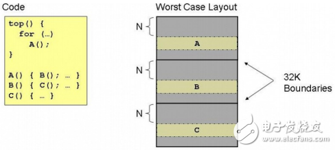
In this scenario, function A calls B, which then calls C, and so on. Because they all map to the same cache location, each call overwrites the previous one, causing unnecessary cache replacements and reducing performance. To avoid this, functions should be arranged in memory in a way that minimizes overlapping cache mappings. The correct arrangement ensures that functions are spaced out, allowing for better cache utilization and improved execution speed.
As shown in the following figure, if the total size of functions A, B, and C is less than 32KB, they can be placed in continuous memory locations without overlap. Even if the total exceeds 32KB, only the part beyond the 32KB boundary would cause cache conflicts, minimizing the impact on performance.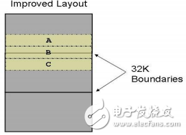
3. Memory Optimization Tool
The tool works by enabling the generation of profiling information during compilation. The compiler inserts additional code into the user’s program to record function calls and their frequencies. After running the executable on a simulator or actual hardware, this data is collected and analyzed. The more test cases you run, the more accurate the optimization result will be.
Once the function call data is gathered, the compiler tool generates an optimized order for function placement. This order is then used to recompile the original code, resulting in a more efficient executable file. Proper memory arrangement can significantly reduce cache conflicts and improve overall performance.
4. Example Tutorial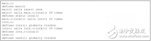
If using CCS, enable the Feedback option in the Build properties and compile normally to generate an executable with built-in profiling code.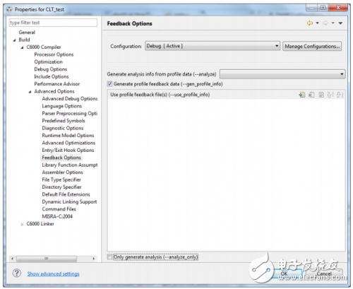
5. Cost-Effective Manufacturing: While introducing advanced features, TOPCon technology maintains a competitive cost structure, making it economically viable for mass production and deployment in large-scale solar power plants.
6. Flexibility in Design: The process is compatible with existing manufacturing lines, allowing for easy integration into current semiconductor fabrication processes without significant capital investment.