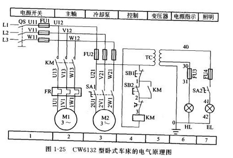
In order to express the design intent of the structure and principle of the production mechanical electrical control system, to facilitate the installation, commissioning, use and maintenance of the electrical system, the electrical components of the electrical control system and their connecting lines are expressed in a certain pattern. This is the electrical control. System diagram. A circuit that connects wires, such as motors, electrical appliances, and meters, according to certain requirements, and implements certain control requirements. The general rules for drawing electrical schematics are as follows: Drawing main circuit When drawing the main circuit, the main control, protection and other electrical equipment, such as circuit breakers, fuses, inverters, thermal relays, motors, etc., should be drawn with thick solid lines according to the specified electrical graphic symbols, and the relevant text symbols should be marked in turn. . Drawing control circuit The control circuit is generally composed of switches, buttons, signal indications, contactors, relay coils and various auxiliary contacts. No matter simple or complicated control circuits, they are generally composed of various typical circuits (such as delay circuits, interlocks). Circuit, sequence control circuit, etc. are combined to control the "start", "run" and "stop" of the controlled equipment in the main circuit to make the equipment in the main circuit work normally according to the requirements of the design process. For a simple control circuit: as long as the function to be realized by the main circuit, combined with the production process requirements and the order of the equipment movements in order, and then carefully drawn. For the complicated control circuit, it is divided into several local control circuits according to the functions completed by each part, and then compared with the typical circuit to find out the similarities, in the principle of simple first, then complicated, first easy and then difficult. Draw each part of the link and find the relationship between each link. Electrical installation wiring diagram specification In general, the electrical installation diagram and schematic diagram need to be used together. The main principles to be followed in drawing an electrical installation diagram are as follows: 1. The electrical installation wiring diagram must be drawn in accordance with the relevant national standards. 2. The position and text symbol of each electrical component must be consistent with the markings in the electrical schematic. The components of the same electrical component (like the contacts, coils, etc. of a contactor) must be drawn together, and the position of each electrical component. It should be consistent with the actual installation location. 3. The electrical connections of electrical components or signals that are not on the same mounting plate or electrical cabinet should generally be connected through the terminal block and connected according to the wiring number in the electrical schematic. 4. A plurality of wires that are the same and have the same function can be represented by a single wire or a wire harness. When drawing the connecting line, the specification, type, color, number of roots and size of the threading pipe should be indicated. Electrical component layout specification The design of electrical component layout drawings should follow the following principles: 1. Electrical component layout must be designed and drawn in accordance with relevant national standards. 2. When the same type of electrical components are arranged, the larger and heavier should be installed under the control cabinet or panel. 3. The hot components should be installed above or behind the control cabinet or panel, but the thermal relays are usually mounted under the contactors to facilitate connection to the motor and contactors. 4. Electrical components, operating switches, and monitoring instruments that require frequent maintenance, tuning, and maintenance should be installed at a high or low level for the staff to operate. 5. Strong and weak electricity should be routed separately. Pay attention to the connection of the shielding layer to prevent interference. The arrangement of electrical components should consider the installation clearance and be as neat and beautiful as possible. recognition methods The general method of looking at the electrical control circuit diagram is to look at the main circuit first, then look at the auxiliary circuit, and use the circuit of the auxiliary circuit to study the control program of the main circuit. 1. Look at the steps of the main circuit The first step: see the electrical equipment in the main circuit. Electrical equipment refers to electrical appliances or electrical equipment that consumes electrical energy. The first thing to look at is that there are several electrical appliances, their types, uses, wiring methods and some different requirements. The second step: to figure out what electrical components are used to control the electrical equipment. There are many ways to control electrical equipment, some are controlled directly by switches, some are controlled by various starters, and some are controlled by contactors. Step 3: Understand the control and protection devices used in the main circuit. The former refers to control components other than conventional contactors, such as power switches (transfer switches and air circuit breakers) and universal transfer switches. The latter refers to short-circuit protection devices and overload protection devices, such as the specifications and specifications of components such as electromagnetic trip units and thermal overload releases in air circuit breakers, fuses, thermal relays and overcurrent relays. In general, after analyzing the main circuit as described above, the auxiliary circuit can be analyzed. Step 4: Look at the power supply. To know the power supply voltage level, whether it is 380V or 220V, is it from the busbar busbar power supply or the power distribution panel, or from the generator set. 2. See the steps of the auxiliary circuit The auxiliary circuit includes a control circuit, a signal circuit, and a lighting circuit. Analyze the control circuit. According to the control requirements of each motor and the executing electric appliance in the main circuit, the other control links in the control circuit are found one by one, and the control circuit is “normalized to zeroâ€, and divided into several local control lines according to different functions for analysis. If the control circuit is more complicated, the circuits that are not closely related to the control such as illumination and display can be excluded to concentrate on the analysis. The first step: look at the power supply. First see the type of power supply. Is it AC or DC? Second. It is necessary to see where the power supply of the auxiliary circuit is connected, and its voltage level. The power supply is usually connected from the two phase lines of the main circuit, and its voltage is 380V. There is also a phase line and a zero line connected from the main circuit, the voltage is single phase 220V; in addition, it can also be connected from a dedicated isolated power transformer, the voltage is 140, 127, 36, 6.3V and so on. When the auxiliary circuit is DC, the DC power supply can be connected from the rectifier, the generator set or the amplifier, and the voltage is generally 24, 12, 6, 4.5, 3V, and the like. The coil rated voltage of all electrical components in the auxiliary circuit must be the same as the auxiliary circuit power supply voltage. Otherwise, the circuit components do not operate when the voltage is low; when the voltage is high, the electrical component coils are burned out. The second step: to understand the use of various relays and contactors used in the control circuit, such as the use of some special structure of the relay, should also understand their operating principles. The third step: According to the auxiliary circuit to study the action of the main circuit. After analyzing the above contents and combining the requirements in the main circuit, the operation process of the auxiliary circuit can be analyzed. The control circuit is always drawn between two horizontal power lines or two vertical power lines in the order of action. Therefore, it is possible to analyze from left to right or from top to bottom. For complex auxiliary circuits, the entire auxiliary circuit forms a large loop in the circuit. In this large loop, it is divided into several independent small loops, each of which controls an electrical device or an action. When a small loop forms a closed loop and a current flows, the electrical components (contactors or relays) in the loop operate, and the electrical equipment is connected or the power is removed. In the auxiliary circuit, the circuit is usually turned on by a button or a transfer switch. The analysis of the control circuit must be carried out at any time in conjunction with the action requirements of the main circuit. Only after fully understanding the requirements of the main circuit for the control circuit can the operating principle of the control circuit be truly grasped, and the operating principle of each part cannot be viewed in isolation, but should be noted. Whether there is a mutual constraint relationship between the various actions, such as interlocking between the positive and negative phases of the motor. Step 4: Study the relationship between electrical components. All electrical components in the circuit are not isolated but are interconnected and mutually constrained. This mutual control relationship is sometimes manifested in a loop, sometimes in several loops. Step 5: Study other electrical equipment and electrical components. Such as rectifier equipment, lighting, etc. Basic steps and precautions for drawing electrical schematics The basic steps of drawing the electrical schematic diagram are: firstly, carefully conceive, and do a good job of the steps to be drawn and the content and layout of the expression; then layout the entire surface, and put all the content to be expressed (cannot be missed), The correct position, primary and secondary, and the actual size of the screen; third, determine the baseline, including the horizontal and vertical baseline; fourth, from left to right, top to bottom, first and second After the first, second, and second, the text is drawn in the order of the text (including the text line); fifth, after careful and detailed inspection, confirm the error without missing the deep drawing, note the text; finally, Seriously, in detail, check and confirm, sign in the title bar, etc. Precautions for drawing electrical schematics 1. The electrical control circuit can be divided into the main circuit and the control circuit according to the current passing through the circuit. The main circuit consists of a circuit from the power supply to the motor, which is the part through which a strong current passes, drawn in bold lines on the left side of the schematic. The control circuit is a circuit that passes a weak current, generally consisting of a button, a coil of an electrical component, an auxiliary contact of a contactor, a contact of a relay, etc., and is drawn on the right side of the schematic by a thin line. 2. In the electrical schematic diagram, the graphics and text symbols of all electrical components must adopt the uniform standards stipulated by the state. 3. Use the drawing method of the electrical component expansion diagram. The components of the same electrical component may not be drawn together, but need to be marked with the same text symbol. If there are multiple electrical components of the same type, you can add a numeric serial number after the text symbol, such as KM1 and KM2. 4. All buttons and contacts are drawn in the original state when there is no external force and no power is applied. 5. The branch lines of the control circuit are arranged in principle according to the order of the actions, and the electrical connection points when the two lines are cross-connected are marked with black dots. Detailed example interpretation The electrical schematic diagram uses graphical and textual symbols to indicate the connection relationship and electrical operating principle of the various electrical components in the circuit. It does not reflect the actual size and installation location of the electrical components. Now take the electrical schematic diagram of the CW6132 horizontal lathe shown in Figure 1-25 as an example to illustrate some basic principles that should be followed in drawing an electrical schematic. 1 Electrical schematic diagrams are generally divided into main circuit, control circuit and auxiliary circuit. The main circuit consists of a circuit from the power supply to the motor, which is the part through which the large current passes, as shown on the left side of the figure (Figure 1, 2, 3, 3). The current passed by the control circuit and the auxiliary circuit is relatively small. The control circuit is generally a coil circuit of a relay and a contactor, and includes contacts of various main electrical appliances, relays, and contactors (such as 4 zones in FIG. 1-25); Auxiliary circuits generally refer to circuits such as illumination, signal indication, and detection (see areas 5, 6, and 7 in Figure 1-25). Each circuit should be drawn from top to bottom and left to right as much as possible in the order of action. 2 The graphic and text symbols of all electrical components in the electrical schematic diagram must adopt the uniform standards stipulated by the state. In the figure, the electrical components are separated, that is, the various components of the same appliance may not be drawn together, but must be marked with the same text symbol. For similar electrical appliances, the number should be followed by a numeric number to indicate the difference (see SB1 and SB2 in Figure 1-25). 3 In the electrical schematic diagram, the movable parts of all electrical appliances are drawn according to the original state, that is, the contacts of the relay and contactor should be drawn according to the state when the coil is not energized; for the controller, the handle should be pressed. Draw in the state of zero position; for the main electric appliance such as button and travel switch, it should be drawn according to the state when it is not subjected to external force. 4 The power line of the power circuit should be drawn horizontally; the main circuit should be drawn perpendicular to the power line; the control circuit and the auxiliary circuit should be perpendicular to the horizontal power line; energy-consuming components (such as coils, solenoid valves, indicator lights, etc.) should be connected The next one side of the power cord, and the various control contacts should be connected to the other power line. 5 should minimize the number of lines and avoid line crossings. When there is electrical connection between the wires, draw a solid dot at the intersection of the wires. According to the layout requirements, the graphic symbol can be rotated and rotated, generally rotated 90% counterclockwise but its text symbol can not be inverted. 6 The voltage, polarity, frequency and phase number of each power supply circuit should be marked on the electrical schematic diagram; some components should also be marked with their characteristics (such as resistance value, capacitance value, etc.); less common electrical appliances (such as location) Pass) also label its operation mode and function. 7 For the convenience of reading the picture, the picture can be divided into several picture areas in the electrical schematic diagram, and the function of each picture area circuit is indicated. Piezoelectric Rings For Ultrasonic Machining
Ultrasonic processing is a special processing tool that uses ultrasonic frequency to vibrate at small amplitudes, and through the impact of the abrasive free of liquid between it and the workpiece on the processed surface, the surface of the workpiece material is gradually broken.
Yuhai company is engaged in produce high performance piezoelectric elements,
Custom Hifu Piezo Parts,Hifu Ultrasonic Focusing Part,Piezo Crystal For Hifu,Cheap Hifu Transducer Zibo Yuhai Electronic Ceramic Co., Ltd. , https://www.yhpiezo.com