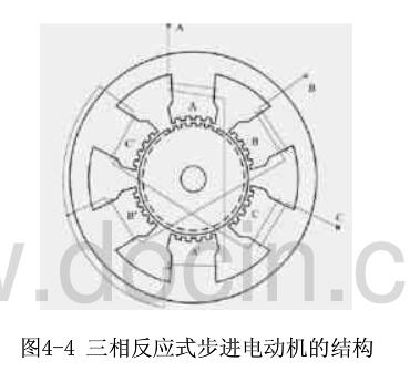
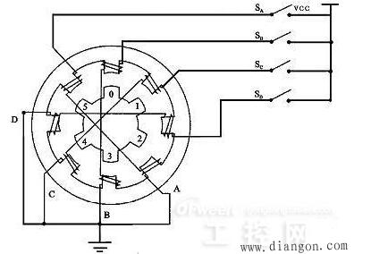
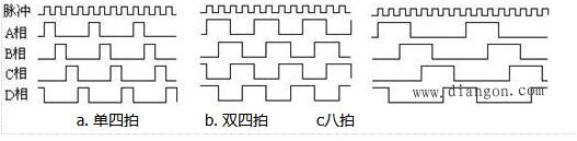
A stepper motor is an open-loop control element that converts an electrical pulse signal into an angular displacement or a linear displacement. Under non-overload conditions, the rotational speed of the motor and the position of the stop depend only on the frequency and the number of pulses of the pulse signal, but not the load. The effect of the change is that a pulse signal is applied to the motor and the motor rotates through a step angle. The existence of this linear relationship, coupled with the fact that the stepper motor has only periodic errors and no cumulative errors, is a feature. It is very simple to use a stepper motor to control the speed and position. This article mainly introduces the structure and working principle of the reactive stepper motor. The three-phase and four-phase reactive stepper motors are used as an example to explain its working principle in detail. Reactive stepper motor is a kind of traditional stepper motor. The magnetic rotor core generates rotation by interacting with the pulsed electromagnetic field generated by the stator. The working principle of the reactive stepping motor is relatively simple. The rotor is evenly distributed with many small teeth. The stator teeth have three excitation windings, and their geometric axes are respectively offset from the rotor tooth axis. The position and speed of the motor are in a one-to-one relationship with the number of pulses (number of pulses) and frequency. The direction is determined by the conductive sequence. The market is generally dominated by two, three, four, and five-phase reactive stepper machines. Reactive stepping motors have many structural forms, and they are divided into single-stage and multi-stage types according to the number of stator core segments. 1ã€Single-stage stepping motor A single-stage stepping motor is a fixed-iron core. Because each phase winding is evenly arranged in the circumferential direction, it is also called a radial split type. It is the most used form of a stepper motor. Figure 4-4 is a radial cross-sectional view of a phase-reactive stepper motor. The stator core is made of laminated silicon steel. The stator poles are of the salient pole type. The pole faces of the poles have small teeth. There are three sets of control windings on the stator, and each set has two series-connected centralized control windings wound on two diametrically opposing magnetic poles, respectively. Each winding is called a phase, three-phase winding connected into a star, so the number of stator magnetic pole is usually twice the number of phases, that is 2p = 2m (p is the number of pole pairs m is the number of phases) the rotor has no windings, along the circumference For a uniform small tooth, the tooth pitch and pitch of the small teeth on the stator pole must be equal, and the number of teeth of the rotor has a certain limit. The advantage of this type of construction is that it is easy to manufacture, the accuracy is easy to guarantee, and the step angle can be made smaller. Easy to get higher startup and operating frequency. The disadvantage is that when the diameter of the motor is small and the number of phases is large, the phase separation in the radial direction is difficult, the power consumption is large, and there is no detent torque when the power is off. 2, multi-step stepping motor The multi-step type stepping motor is a fixed rotor core divided into m segments along the axial direction of the motor. Since each phase winding is distributed along the axial direction, it is also called an axial phase split type. According to the structural characteristics of its magnetic circuit there are two, one is the main magnetic circuit is still radial, the other is the main magnetic circuit containing the axial part. 1, higher torque moment of inertia ratio 2, high stepping frequency, fast frequency response 3. It can rotate freely when it is not energized, its structure is simple and its service life is long. 1. The working principle of three-phase reactive stepper motor Rotation: If phase A is energized and phases B and C are not energized, tooth 1 is aligned with A due to the magnetic field, (rotor is not subject to any forces below). If phase B is energized and phases A and C are not energized, tooth 2 should be aligned with B. At this time, the rotor is moved to the right by 1/3 inch. At this time, tooth 3 and C are offset by 1/3 inch and teeth 4 and A. The offset (ã¦-1/3ã¦) = 2/3ã¦. If phase C is energized, phases A and B are not energized, and tooth 3 should be aligned with C. At this time, the rotor is again moved to the right by 1/3 inch. At this time, tooth 4 and A are offset by 1/3 inch. If phase A is energized, phases B and C are not energized, tooth 4 is aligned with A, and the rotor is moved one third of the way to the right again. This way A, B, C, and A are respectively energized. Teeth 4 (ie, tooth 1) ) Move to phase A. Rotate the motor rotor to the right by one tooth pitch. If you press A, B, C, A... power continuously, the motor will rotate 1/3 turns per step (per pulse). If you press A, C, B, A ... power, the motor will reverse. It can be seen that the position and speed of the motor are in a one-to-one correspondence between the number of times of conduction (the number of pulses) and the frequency. The direction is determined by the conductive sequence. However, due to considerations such as torque, stability, noise, and reduced angles. The conductive state of A-AB-B-BC-C-CA-A is often used, which changes the original 1/3 inch to 1/6 inch. Even through a combination of two-phase currents, the 1/3 turns into 1/12 turns and 1/24 turns. This is the basic theoretical basis for motor subdivision. It is not difficult to put out: The motor stator has an m-phase excitation winding, and its axis is offset from the rotor tooth axis by 1/m, 2/m...(m-1)/m, 1 respectively. And the electrical conduction can be controlled positively and negatively according to a certain phase sequence motor - this is the physical condition of rotation. As long as this condition is met, we can theoretically manufacture stepper motors for any phase. Considering cost and other considerations, there are generally two, three, four, and five phases in the market. Torque: Once the motor is energized, a magnetic field (flux Ф) will be generated between the stator and rotor. When the rotor and the stator are offset by a certain angle, the force F is proportional to (dФ/dθ) S. The magnetic flux Ф=Br*S Br is magnetic, S is Magnetically conductive area F is proportional to L*D*Br. L is the effective length of the core, and D is the rotor diameter Br=N.I/RN.I is the number of ampere turns of the excitation winding (current times turns). R is the reluctance. Torque = force * radius torque and the motor effective volume * ampere * magnetic density is proportional to (only consider the linear state) Therefore, the greater the motor effective volume, the greater the number of excitation ampere, the smaller the air gap between the stator and rotor, the motor torque The bigger, and vice versa. 2ã€Four-phase reactive stepper motor working principle The stepper motor is a four-phase stepper motor and is powered by a unipolar DC power supply. As long as each phase winding of the stepping motor is energized at an appropriate timing, the stepping motor can be step-rotated. FIG. 1 is a schematic diagram of the working principle of the four-phase reactive stepper motor. At the beginning, the switch SB is turned on and the SA, SC, and SD are disconnected. The phase B pole and the teeth of the rotors 0 and 3 are aligned. At the same time, the teeth of the rotor's No. 1 and No. 4 are misaligned with the magnetic poles of the C and D phase windings. No. 2, No. 5 teeth and D, A phase winding magnetic pole wrong teeth. When switch SC is turned on and SB, SA and SD are disconnected, the rotor rotates due to the magnetic field lines between the magnetic lines of the C-phase winding and the teeth of No. 1 and No. 4. The magnetic poles of the No. 1 and No. 4 teeth and the C-phase winding are aligned. . The 0th and 3rd teeth and the A and B phase windings produce the wrong teeth, and the 2nd and the 5th teeth are misaligned with the magnetic poles of the A and D phase windings. By analogy, A, B, C, D four-phase winding power supply in turn, then the rotor will turn in the direction of A, B, C, D. Four-phase stepping motor can be divided into single four-shot, double-four-shot, and eight-shot three working modes according to different power-on sequence. Single four-shot and double-four shots have the same step angle, but the single four-shot rotation torque is small. The stepping angle of the eight-shot work mode is one-half of a single quadruple shot and double quadruple shots. Therefore, the eight-shot work mode can maintain a high rotational torque and improve the control accuracy. The power supply timing and waveforms for the single four-shot, double-four-shot, and eight-shot operation modes are shown in Figure 2.a, b, and c, respectively: "What is the difference between hybrid stepper motor_hybrid stepper motor and reactive stepper motor" "Detailed structure and working principle of HB type hybrid stepper motor" "One article to understand the relationship between HB hybrid stepping motor and the number of phases, the number of teeth of the rotor, the number of the main pole"
Yuhai Company is engaged to research
and development of piezoelectric products
and related piezoelectric products, the related piezoelectric products includes the piezo sensors and transducer.
The ultrasonic transducer is a kind of transducer that converts the ultrasonic signal into electric signal, or vice versa. Ultrasound transmitter and receiver is a transducer that can transmit and receive ultrasound. Ultrasound sensor is a kind of sensor, in essence, it is also a transmitter and receiver. The working principle of this kind of equipment is similar to that of radar and sonar. Active ultrasonic sensors can emit and receive reflected waves, and determine the distance of the target by measuring the time interval between transmission and reception. Passive ultrasonic sensor is actually a microphone that can convert ultrasonic signal into electrical signal.
Ultrasonic Sensor,Piezo Sensor,Ultrasonic Piezo Disc,Ultrasonic Piezo Elements Zibo Yuhai Electronic Ceramic Co., Ltd. , https://www.yhpiezo.com
According to the working principle and materials used, the ultrasonic transducer has piezoelectric transducer, electrostatic transducer (capacitive transducer), magnetostrictive transducer, electromagnetic acoustic transducer, mechanical transducer and other types [1].