Environmentally Friendly Polyolefin Heat Shrink Tubing
Product description:
Environmentally friendly polyolefin heat shrink tubing is made of polyolefin material, Thin wall cable protection heat shrink tubing it has the function of insulation and protection.Flexible thin wall polyethylene heat shrink tubing it applies to electric components, coating of the wire harness, and protection of the terminal junction of the electric wire and cable, at the same time, thin wall heat shrink tubing it also has the function of color identification. It's widely used in electrics, electronic industry, electrical industry, etc.
Feature and benefit:
Our Shrink Tubing feature and benefit :Shrink ratio is 2/1 with flexible, low shrink temperature,excellent physical and electrical performance.
Free of PCBs, PCPs, polybrominated biphenyls (PBBs), polybrominated biphenyl oxides and ethers (PBBOs, PBBEs and PBDEs) and toxic heavy metal compounds, which are classified as environmentally hazardous substances. Conform to European RoHS environmental directive.
Our Thin Wall Shrink Tubing Feature and Benefit:
Shrink ratio is 2/1 with flexible, low shrink temperature,excellent physical and electrical performance.
Up to standard: Approvals
Meet UL224 125 degrees Celsius 600V VW-1
Operating Temperature Range:
Nonstandard: Brown, orange, violet, gray
Nonstandard size:Special sizes are available upon request.
Product picture:
Avg. Wall thickness = (max. Wall thickness = min.Wall thickness)
Thin Wall Heat Shrink Tubing,Ultra Thin Wall Heat Shrink Tubing,Thin Heat Resistant Shrink Tubing,Thin Wall Polyolefin Heat Shrink Tubing,Waterproof Heat Shrink Tubing,Heat Shrinking Thin Wall Tubing Dong Guan KE YU New Material Technology co.,LTD , https://www.insulationtubing.com
At present, the geomagnetic sensor IST8310 of 3×3mm LGA package of Aisin Technology has a market share of over 80% in the drone market. The drone products of the big manufacturers that can be seen on the market are all using Aisheng Technology. The geomagnetic sensor is the benchmark for geomagnetic sensors used in mainstream drones today, so the drone test samples mentioned below are also of this model. It is well known that the magnetic field is inversely proportional to the distance of the distance, and the internal electronic compass of the drone is close to the rest of the electronic components. Therefore, the unreasonable arrangement of the internal system causes the electronic compass to be interfered by the magnetic field, which is often the case. Ignored by the designer. In order to avoid the crash situation caused by the electronic compass failure during the actual flight, after the drone completes the hardware proofing or trial operation, the actual flight is not required, and the accurate analysis of the electronic compass can be completed through the test. In the pre-test, the UAV was first fixed with wood, plastic, foam, and aluminum materials without magnetic fields. It is worth noting that the UAV is best equipped with a casing and a rotor, which can simulate the real flight time to the maximum extent. Case. Considering that the motor and circuit of the drone may be sources of magnetic interference, we need to export the data of "X-axis magnetic field size, Y-axis magnetic field size, Z-axis magnetic field size, throttle size" from the I2C interface for storage and comparison. As an important basis for subsequent analysis. 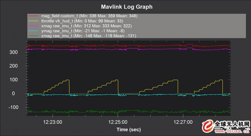
Figure 1: The internal system design of the drone is reasonable and stable when the throttle is opened.
During the test, it is only necessary to adjust the throttle from off to on and advance step by step, perform several rounds of repeated tests, and finally summarize the data of several rounds of tests to the same time axis for presentation. Since the drone has been fixed and there is no azimuth movement, theoretically, no matter how the throttle is adjusted, the numbers of the magnetic fields of the X, Y, and Z axes should not change much, showing a stable situation. But in fact, because the electronic compass assembly itself and the system will have noise, the data lines will have a certain degree of up and down jitter, but the trend should be constant. The smaller the jitter, the more stable the moving path. Similarly, when the throttle is opened or closed, a surge circuit is actually generated, and the magnetic field also fluctuates. The smaller the data line jitter, the better the position of the electronic compass is placed, and the overall design of the system is reasonable. As shown in Figure 1, an internal system with the correct design of the drone experienced four throttle changes in the test, from zero to 100%, but the pointing angle, X-axis, Y-axis, and Z-axis magnetic fields did not fluctuate strongly. The data will fluctuate slightly when the throttle is turned on or off. It shows that the electronic compass will not be affected by the magnetic field interference in the system during operation, and the drone will have better handling performance. 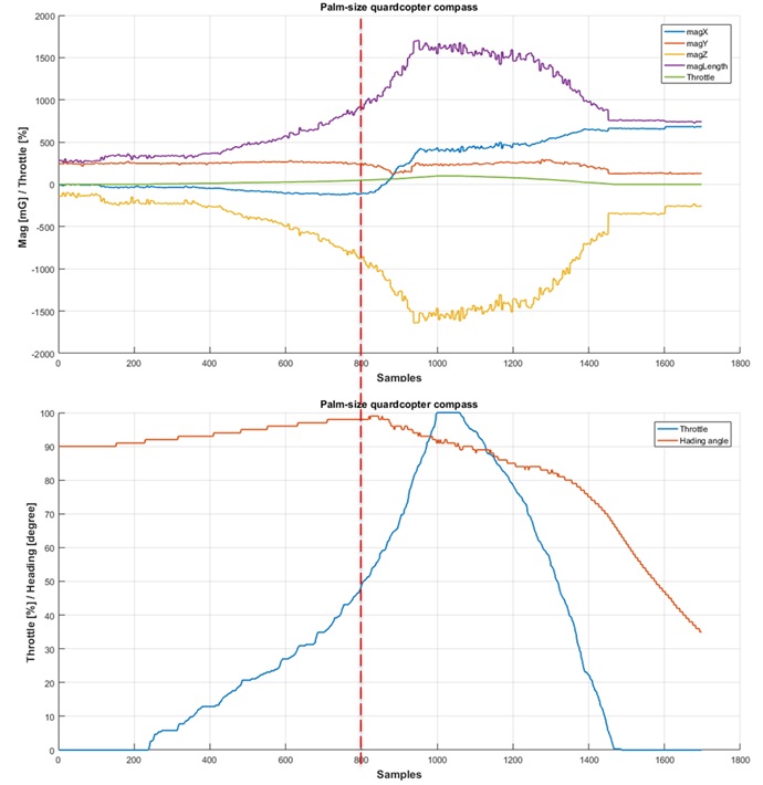
Figure 2: There is a problem with the internal system design of the drone. The magnetic field fluctuates greatly when the throttle is opened.
Contrary to Figure 1, if there is a problem with the internal system design of the UAV, after the same test procedure, the data image will show significant deviation and fluctuation. As shown in Figure 2, the blue line in the lower picture in Figure 2 represents the throttle force. The orange line represents the pointing angle of the drone. Since the drone has been fixed, the angle of the pointing is not due to the increase of the throttle. Large reduction and change, but as can be seen from Figure 2, the UAV pointing angle in the test has deviated significantly, which indicates that the magnetic field induction of the electronic compass has changed. In the upper picture in Figure 2, it can be seen more clearly that the blue line (X axis), orange line (Y axis), yellow line (Z axis) have different degrees of fluctuation, and the Z axis has the largest fluctuation, X axis times. It. With this clue, you can further analyze where the source of the magnetic field changes. If the tester still has questions, visit the official website of for further information.
After the above detection process, if the designer can successfully find the magnetic interference source inside the drone, and repeat the above test again, the data image obtained by the test should be consistent with Figure 1, indicating the magnetic interference problem of the internal system of the UAV. It has been solved that the drone electronic compass can operate stably when the throttle changes. Through the solution given by Aisheng Technology, the drone can be screened in the early stage without actual flight, which not only reduces the test threshold, but also avoids the drone being out of control due to the failure of the electronic compass to operate normally. Machine risk provides a new way of thinking for the industry.
Source: Submission of Aisheng Technology Co., Ltd. Address: 2-1-12, Qiujia Hutong, Xinjiekou, Xicheng District, Beijing
Mobile: +86 13701103845
Email:
b) Minimum shrink temperature: 60 degrees Celsius
c) Minimum full recovery temperature: 100 degrees Celsius
Ordering Information:
Color:Standard: Shiny black, clear, white, red, blue , yellow, green
Standard packaging:On spools. Cut pieces are available upon request.
Ordering description:Specify product type, size (mm or inch) and color.


Correctly judge the UAV pointing fault to keep the electronic compass away from magnetic interference
The electronic compass is an important component of the drone product and carries the function of guiding the absolute position of the drone . For the average designer, it is often difficult to correct the electronic compass, the calibration demand is too frequent, the dynamic, high-speed operation suddenly deviates, and no matter how the electronic compass is corrected, it cannot operate normally. The main reason for the above failure is that the electronic compass is subject to magnetic field interference. For this problem, the world's leading magnetic sensor company, Aisheng Technology, has given a simple and efficient solution.