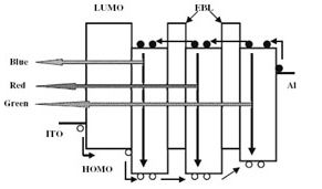
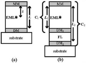
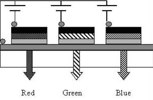
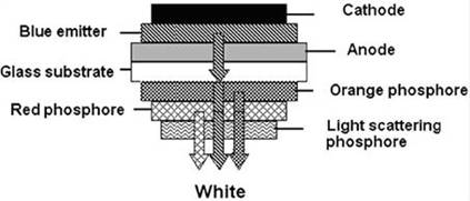
Abstract: White light organic light-emitting diode (WOLED) is considered as an alternative light source for traditional white light sources. They are efficient solid-state light sources, and electro-optical conversion efficiency has surpassed incandescent lamps. 1. Introduction <br> The world consumes a huge amount of electricity every year. In all electrical energy consumption, lighting energy accounts for 20% of total electrical energy production. Fluorescent and incandescent lamps are the most common traditional sources of illumination, and 40% of the electrical energy used for illumination is consumed by them. Incandescent lamps turn 90% of electrical energy into heat, and fluorescent lamps perform better. They convert 70% of the energy consumed into light. Typical luminous efficiencies for incandescent and fluorescent lamps are 13-20 lm/W and 90 lm/W, respectively [1]. So in order to save energy in the world, one way is to find a replacement for traditional light sources. Researchers have spent more than a decade researching semiconductor light-emitting diodes with better performance. Light-emitting diodes of red, green, blue and other colors made of inorganic materials have long appeared in the market, and they are widely used in traffic lights, automobile taillights and other small applications. Inorganic white light-emitting diodes have also appeared on the market, but their prices are relatively high compared to ordinary lighting applications. Now a new competitor of lighting sources has come to the market, which is based on organic semiconductor materials. In the past decade, OLEDs have shown strong competitiveness in terms of display technology compared to liquid crystals. Since the discovery of efficient electroluminescence in tris (8-hydroxyquinoline) aluminium (Alq3) [2] in 1987 and poly(p-phenylene vinylene) (PPV) [3] in 1990, OLED has become the most attractive. Display technology. It has the advantages of simple preparation, short response time, high brightness, wide viewing angle, low driving voltage, most likely to be applied to flexible substrates and full color display. OLED displays are durable, efficient, and can be fabricated onto flexible substrates, such as plastic and paper surfaces, and the resulting display can be bent or rolled up. Unlike liquid crystals, OLEDs are self-illuminating and do not require backlighting, which makes OLED displays thinner and lighter. An OLED is a multilayer film device consisting of an active charge transport layer sandwiched between two film electrodes and a light-emitting layer, at least one of which is transparent. In general, indium tin oxide (ITO) with a high work function (~4.8eV), low sheet resistance (~20 Ω / □) and transparent to visible light is used as the anode, and the cathode generally uses a low work function metal. For example, Ca, Ma, Al or their alloys Ma: Ag, Li: Al. An organic layer having good electron transport properties and hole blocking properties is placed between the cathode and the light-emitting layer. Likewise, a hole transport layer and an electron blocking layer are used between the anode and the light-emitting layer. When the external is biased, electrons and holes are injected from the cathode and anode of the OLED, respectively. Under the action of an external electric field, electrons and holes migrate in opposite directions, and excitons are formed in the light-emitting region, and the exciton decays to radiate light outward. The migration dynamics and properties of excitons are not discussed here. White OLED technology has attracted considerable attention due to its use in general-purpose solid-state lighting and in flat panel displays as liquid crystal backlights. In the preparation of full-color displays, the three primary colors are equally important, but white light emission has gained more attention because any desired color range can be obtained by filtering white light. The first white OLED device was made in 1993 by Kido and his colleagues. This device contains compounds that emit red, green, and blue light to produce white light. But there are also some problems at the same time. The device is less than 1 lm/W, and the device requires a large drive voltage and is quickly burned out. But now the efficiency of these devices is improving very quickly. The efficiency improvement in traditional LED, nitride LED, and white OLED is shown in Figure 1. Figure 1 LED efficiency progress annual table 2, OLED excitation white light <br> Lighting white light should have a good color rendering index (> 75) and good color coordinate position (close to the International Lighting Association's chromaticity diagram (0.33, 0.33) point). The generation of white light from an OLED can be roughly classified into the following two ways. (a) Wavelength conversion Blue or ultraviolet light emitted from an OLED is used to excite several phosphorescent materials, and light of different colors emitted by each material is mixed together to obtain white light having a rich wavelength range. This technique is called down conversion of phosphorescence. (b) Color mixing This method uses a plurality of light-emitting layers in one device, and uses different colors of light emitted by different light-emitting layers to produce white light. White light can be obtained by mixing 2 complementary colors (blue and orange) or three primary colors (red, green, blue). A typical multi-layer structure is used to generate light of a plurality of colors, and various colors are mixed to obtain white light. The main methods are (a) a multilayer structure including red, green, and blue light-emitting layers (b) F ̈orster / Dexter energy conversion A good quality white light does not require a breakthrough, but obtaining a stable white light is still a research and development hotspot. 2.1 Color Mixing 2.1.1 Multilayer Film Device Structure: This method of obtaining white light is to obtain white light by mixing light emitted simultaneously in two or more light emitting layers. This technique is based on continuous deposition or control of co-evaporation and exciton recombination zones of different materials. This structure contains many organic-inorganic interfaces, and the energy barrier at the interface increases the difficulty of carrier injection and generates Joule heat. Therefore, in order to reduce the charge injection energy barrier and Joule heat at the organic-inorganic interface, the luminescent material is selected such that the highest occupied molecular orbital and the lowest molecular vacant orbit of the adjacent luminescent material need to match each other. The luminescence of the device depends on the composition and film thickness of each layer, and precise control of the composition and film thickness of the luminescent layer is required to achieve color balance. The recombination region of the excitons is controlled by adding a barrier layer that blocks only one type of carrier between the hole transport layer and the electron transport layer. So that the recombination zone occurs in two or three different luminescent layers. The result of this is that light is emitted in different luminescent layers (Figure 2). Figure 2 Schematic diagram of multi-layer white OLED structure The light emitted from the red, green, and blue light-emitting layers is balanced by controlling the composite current in different organic layers to obtain white light of a desired purity. Deshpande et al. [4] obtained white light by performing successive energy level conversions in different layers. The fabricated device structure was ITO /α -NPD /α NPD:DCM2(0.6–8 wt%) / BCP / Alq3 / Mg:Ag(20:1) / Ag . Here, 4,4_bis[N-(1-napthyl-N-phenyl-amino)]biphenyl (α NPD) was used as the hole injection layer. α NPD: DCM2 (2, 4-(dicyanomethylene)-2-methyl-6-[2-(2, 3, 6, 7-tetrahydro-1H, 5H benzo[I,j]quinolizin-8-yl)vinyl] -4H-pyran) is used as a hole transport layer and a light-emitting layer. The 2,9-dimethyl-4,7-diphenyl-1,10-phenanthroline (BCP) layer is deposited to block holes, and Alq3 is used as A green light-emitting layer and an electron transport layer, a Mg:Ag alloy and a subsequent thick Ag layer thereof are used as the anode. The maximum brightness reported by this device is 13500 cd m -2 , the maximum external quantum efficiency is greater than 0.5%, and the luminous efficiency is 0.3 lm /W. Recently, Wu et al. [5] reported an OLED device with a dual light-emitting layer, and the device studied both the use of a barrier layer and the absence of a barrier layer. In addition to exhibiting better performance, the device with a barrier layer has an external quantum efficiency of 3.86%. The color of the light excited by these devices is strongly dependent on the thickness of the luminescent layer and the applied voltage. A disadvantage of this technique is that the preparation process is complicated and there is a large amount of waste of organic materials, resulting in relatively high manufacturing costs. Another way to obtain white light excitation from multilayer OLED devices is to use a multi-quantum well structure [6] (Fig. 3), which includes two or more light-emitting layers separated by a barrier layer. Electrons and holes tunnel through the barrier of the barrier layer and are evenly distributed into different quantum wells for illumination. The energy level matching requirements of different organic materials in this system are not very strict. Excitons form in different wells, decay, and emit different colors of light in their own wells. The quantum well limitation of carriers increases the possibility of exciton formation, preventing excitons from moving to other regions or transferring their energy to other regions. However, this method is very complicated and it is necessary to optimize the thickness of various light-emitting layers and barrier layers. This multilayer structure requires a relatively high operating voltage due to the combined thickness of many layers. Fig. 3 Schematic diagram of white OLED structure of multi-layer quantum well structure 2.1.2 Donor-Acceptor System The excitation energy can be tunneled from the high energy material to the low energy acceptor material by doping the narrow band gap acceptor molecules into the wide bandgap donor material. In such a system, if the doping concentration is maintained at a certain value, the donor's emission can be neglected, and the acceptor's emission dominates. In this type of launch, all of the donor's energy is transferred to the recipient. Another alternative to this system is the incomplete transfer of energy, in which the illumination comes from both the donor and the acceptor areas. By bringing the light emitted by the donor and the recipient to a suitable ratio, white light can be emitted. The donor-acceptor system that produces white light can be either a single doping in a single layer or multiple layers [7], or it can be doped with multiple impurities in a single layer or multiple layers [8]. In order to obtain stable white light, the doping concentration needs to be precisely controlled. The dopant material can be a phosphorescent or fluorescent material in nature, and the doping sites can be excited directly or by energy/charge transfer from the donor molecule. 2.1.3 White Light Emitting of a Single Emission Layer Structure The fabrication process and illumination of the devices discussed above are very complex, and many parameters need to be optimized for better color rendering and high luminous efficiency. Due to the number of base layers that are used to perform specific functions, the thickness of the device is increased, so that the device must have a high driving voltage. In a white organic light emitting diode, in order to lower the driving voltage, the thickness of the device must be reduced. These multi-layered complex structures can be solved by a single layer of illumination. A single-layer white light-emitting diode device includes only one organic light-emitting layer. It has been reported by many people to dope different dyes or to mix two or more polymers in a blue light-emitting organic layer to obtain white light. The greatest benefit of an OLED device having only one illuminating region relative to other OLED devices is that the emitted light has better color stability. However, one disadvantage of this method is that due to the different energy transfer speeds between the different doped materials, the final result is a color imbalance. The high-energy part (blue light) can easily transfer energy to the green and red emitters, and the green emitter can transmit energy to the red emitter. If the emitters of the three colors are at the same concentration, the last red light will dominate. Therefore, the doping ratio must be blue light > green light > red light, and a good balance needs to be achieved. Recently, Shao et al. [9] demonstrated that white OLEDs using a uniform donor single luminescent layer have high color stability. D'Andrade et al. [7] reported a white OLED with only one luminescent layer. The luminescent layer contains three metal organic phosphorescent dopant materials: tris(2-phenylpyridine) iridium(III) [Ir(ppy)3] as a green emitter, iridium (III)bis(2-phenylquinolyl-N, C2 _ ) (acetylacetonate) [PQIr] As a red emitter, iridium(III)bis(4 _ , 6 _ -difluorophenylpyridinato) tetrakis(1-pyrazolyl)borate [FIr6] acts as a blue emitter. These three materials are simultaneously co-doped in the wide band gap donor material p-bis(triphenylsilyly)benzene (UGH2). This white OLED device has a maximum efficiency of 42 lm/W, a color rendering index of 80, and a maximum external quantum efficiency of 12%. In order to obtain white light, the dye is not an essential material. Mixtures of polymers can also be done. Recently, Gong et al. [10] successfully prepared a white OLED device using a mixture of { PFO-ETM and PFO-F (1%) } and [Ir(HFP) 3] as the light-emitting layer. The device's luminous intensity at 25V reached 10,000 cd. 2.1.4 Microcavity Structure A microcavity is a pair of mirrors with a high degree of reflection coefficient at a micron pitch. In 1994, Dodabalapur and his collaborators at Bell Labs fabricated electronic devices by placing Alq and an inert material into two reflective surfaces to form microcavities. In the traditional structure, light can run out in all directions. In a microcavity structure, light can only be emitted from one end of the microcavity structure, thereby increasing the efficiency of the device. By changing the thickness of the layer, unwanted light can be filtered out and light of any desired wavelength can be obtained. LEDs with microcavity structures have higher efficiency and use less current for longer lifetimes. The microcavity structure can be used to optimize the color of light. A white light OLED using a microcavity structure is an example of light color optimization. The microcavity resonator is the most effective way to enhance the brightness of monochromatic LEDs [11,12]. The use of microcavity structures in OLEDs to narrow the luminescence spectrum and enhance luminescence intensity has been reported [13]. Then, since the light emitted after passing through it is single-frequency, there is nothing to do with the white OLED. Dodabalapur et al. [14] achieved control of OLED luminescence by using multiple modes of resonant cavities, allowing different light emitted by materials through different resonant modes to be mixed to obtain white light. In the microcavity structure, the luminescent layer is implanted in the middle of a two-layer metal mirror or a metal mirror and a partially reflected bottom mirror surface containing distributed Bragg reflections [15]. The microcavity structure produces a strong modulation of the spectrum. The distributed Bragg structure contains two mirror layers with different reflection coefficients that provide tunable luminous efficiency over a specific wavelength range. The standing wave is generated while the device is operating, and the wavelength of the standing wave depends on the length between the mirrors in the microcavity structure and the reflectivity of the mirror. Shiga et al. [16] prepared a modified Fabry–Perot resonator containing two microcavity structures at different distances. (Figure 4, where MM, DM, EML, and FL represent the metal mirror, insulator mirror, illuminating layer, and filter layer, respectively), and the light emitted from the microcavity structure can produce white light. The disadvantage of this method is that the color of the light changes as the viewing angle changes. This shortcoming limits the application of microcavity structures in white OLEDs. Figure 4 Microcavity concept (a) Ordinary microcavity structure (b) Multi-wavelength resonant microcavity 2.1.5 The use of a vertical/horizontal laminate structure to produce white light is similar to liquid crystal panel display technology. The three primary color pixels are independently arranged in a horizontal or vertical pattern (see Figure 5). In the horizontal stacking pattern, separate color emitting pixels are deposited in the form of dots, squares, circles, thin lines or thin strips. The light in the wavelength range to be obtained is mixed, and as a result, white light is obtained. Because each color component is deposited in a separate location, different color pixels can reduce the aging speed by changing the operating current. Each pixel can be optimized for maximum efficiency at the lowest operating voltage. Similarly, the lifetime of the device can be extended to a maximum by reducing the area of ​​the pixel. Laminated OLED devices are a good candidate for light sources because stacked devices can achieve twice or even three times their current efficiency relative to single-emitting OLED devices. Matsumoto et al. [17] reported that the laminated structure of the red and blue devices was pink. This laminated structure can obtain light of various colors. It is expected that a white OLED of a stacked structure can achieve higher brightness and efficiency than a conventional white OLED. Recently, Sun et al. [18] reported an efficient stacked white light OLED with an anode cathode layer added between the blue light emitting layer and the red light emitting layer. This anode cathode layer is used as an intermediate electrode, and white light can be obtained by adjusting the bias applied to the two light-emitting layers to a suitable ratio. The device they reported had a maximum illumination of 40,000 cd m -2 at 26 V and a position in the color coordinates of (0.32, 0.38). The luminous efficiency at 28 mAcm -2 was 11.6 cdA -1 . Figure 5 (a) Horizontal (b) schematic diagram of a white laminated OLED with a vertically stacked structure Kido found that the brightness of the laminated structure consisting of N luminescent layers is N times the brightness of a single luminescent layer device. This rule is attractive for white OLEDs that want to achieve high efficiency. Recently, Chang et al. [19] prepared two white OLEDs comprising a stacked structure and a comparative device for comparison, wherein an Ag:Alq 3 /WO 3 connecting layer was used in the middle of the device of the laminated structure. In these devices, white light is obtained by mixing blue light and yellow light. The device 1 is a laminated structure of a yellow light emitting layer and a blue light emitting layer. Device 2 is a stack of 2 device 1 structures. Device 2 showed better performance than Device 1 and the comparison device. A noteworthy amplification was observed in Device 2, which achieved the highest efficiency of 22 cdA -1 , which is almost three times the efficiency of the comparator. This is the result of the microcavity effect, which enhances the amount of light propagating forward. So when the two devices are connected, the efficiency of the device will increase. It has also been found that as the number of luminescent layers increases, the driving voltage also increases. Device 2 is the most unstable, while the contrast device shows the longest half-life. This is because device 2 suffers from a higher driving voltage than device 1 and the comparator. Since the laminated device connection layer is a non-ohmic contact, there may be a thermal breakdown process in the stacked structure device. At 100 cdm-2, the half-life of device 2 is expected to reach 80,000 hours. In these stacked structure devices, the intensity and color of the light are also greatly related to the viewing angle. This dependence of illumination intensity and color on viewing angle is due to microcavity effects. Therefore, it is very important to have a better optical design of the laminated structure device. 2.2 Wavelength Conversion In several ways in which OLEDs achieve white light emission, the poor color stability of the device due to the different lifetimes of different types of light-emitting layers is a common problem. The use of a wavelength down conversion method for phosphorescent materials to emit white light may be a good alternative. In this technique, a blue OLED is bonded to one or more layers of phosphorescent material, with inorganic light scattering particles in between one of the phosphor layers. A phosphor layer is applied to the back of the blue OLED. Some of the blue light emitted by the device is not wavelength-converted and passes directly through the phosphor layer. The remaining part is used to excite the phosphorescent material to excite different materials to obtain different colors of light. These different colors of light and untransformed blue light Mixing gives the widest, most wavelength-rich spectrum. Here only the blue luminescent layer conducts charge and is the only active layer that is directly excited. Once excitons are generated, they excite other phosphorescent materials, resulting in other complementary colors needed to obtain white light. As the blue luminescent layer ages, the emitted blue light also attenuates, and the light emitted from the phosphorescent material associated with it is also proportionally attenuated because the intensity of the light emitted in the phosphorescent material is directly related to the blue luminescent layer. Therefore, in the wavelength down conversion technique, there is no differential color aging problem. The color of the luminescence can be adjusted by changing the doping concentration and thickness of the phosphor layer. Figure 6 is a schematic diagram of the wavelength down conversion mechanism of a phosphorescent material. White light emission can also be obtained by combining ultraviolet light with red, green and blue phosphorescent materials. At this time, ultraviolet light excites several phosphorescent materials, each of which emits light of a different wavelength, and the light is mixed to obtain white light. This technique has good color stability, but the reduction in efficiency due to the wavelength conversion process is a major drawback of this technology. Fig. 6 Schematic diagram of the working principle of the device for realizing white light by the wavelength down conversion method Professor Junji Kido of Yamagata University in Japan is an expert in OLED. He and his colleagues have done a lot of work on white OLEDs, and have made great improvements in device efficiency, half-life and device characteristics. The biggest contribution of the Yamagata and Forrest groups was the transition from fluorescent materials to phosphorescent materials. In phosphorescent materials, both singlet excitons and triplet excitons can be combined to emit light, and the device can achieve higher efficiency. 3. Summary <br> In order to make the luminous efficiency of white OLEDs comparable to existing lighting resources, there is still a lot of work to be done. The imbalance of carriers in the light-emitting layer is a major cause of low luminous efficiency and high operating voltage of the device. Carrier injection, thickness, and material transparency are important in achieving maximum exciton recombination efficiency in the luminescent layer and enhancing device efficiency. The aging time problem of different luminescent materials is another problem that needs to be concerned about white OLEDs. Different luminescent materials have different aging times, and the white light quality of the device changes toward the most stable color as the working time of the device is extended. This problem can be considered by solving the problem of designing the device so that the material has the same aging rate, making the aging effect uniform for the entire device, or by designing a single layer of luminescent layer that can emit white light. Devices with a single luminescent layer also require attention, which has advantages in large area, low thickness, low cost, and flexible substrate preparation. The surface area of ​​the device is now only on the order of a few square inches. In order to achieve application in lighting, flat panel displays need to be on the order of a few square feet. Cost is another important factor that white OLEDs are accepted by the general lighting market. However, in order to reduce costs, it is difficult to prepare a device using vacuum deposition. Therefore, the focus should be on the use of spin-on or inkjet printing technology to prepare white OLED devices, so that the cost can be greatly reduced. The problem with this solution is mainly the carrier injection imbalance and insufficient polymer purity, and the maximum efficiency of the device is less than 15 lm/W. Dendrimers may be a way to address the preparation of white OLEDs. Dendrimers is a mixture of small organic molecules and polymers. It combines the advantages of both, with high-efficiency phosphorescent recombination centers for small molecules, and can also be prepared by spin coating. This makes it possible to reduce the cost of white OLED fabrication by using printing technology. But so far, we have not seen any reports on the application of Dendrimers in white light. At present, white OLEDs still face many challenges. In order to achieve the goal, there are still many researches to be done on the preparation technology. Whether the final white OLED can replace the fluorescent tube, whether the preparation cost is low enough is still a problem. At present, more and more people are interested in the research of white OLED, and the performance is gradually improving. White OLED must have a bright future. references Editor: China Lighting Network / Leaves Coin Operated Soccer Table,Coin Operated Foosball Table,Coin Operated Football Table Tengbo Sports Co., Ltd. , http://www.shpooltables.com
Recently, great progress has been made in the structure of devices and the synthesis of new materials. Here, the methods from organic light-emitting diodes (OLEDs) to obtaining white organic light-emitting diodes, their advantages and disadvantages, and their recent progress are briefly introduced. The problems in device structure and related device design are also discussed. 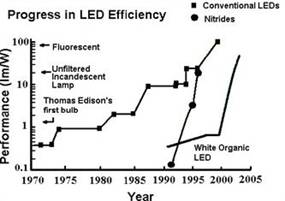
(c) Microcavity structure (d) White light is obtained by a vertical/horizontal laminate structure (e) Different luminescent materials are mixed or doped into a mixed layer. In the color mixing technique, since there is no use of a phosphorescent material, loss due to wavelength conversion does not occur, and this technique has the potential to achieve higher efficiency. The various methods are discussed in detail below. 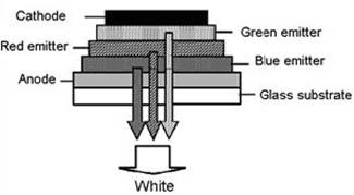
Optoelectronics Industry Development Association (OIDA) 2002 Organic light emitting diodes (OLEDs) for general illumination update 2002 Report August
Tang CW and VanSlyke SA 1987 Appl. Phys. Lett. 51 913
Burroughes JH, Bradley DDC, Brown AR, Marks RN, Mackay K, Friend RH, Burn PL and Holmes AB 1990 Nature 347 539
Deshpande RS, Bulovi? V and Forrest SR 1999 Appl. Phys. Lett. 75 888
Wu YS, Hwang SW, Chen HH, Lee MT, Shen WJ and Chen CH 2005 Thin Solid Films 488 265
Liu S, Huang J, Xie Z, Wang Y and Chen B 2000 Thin Solid Films 363 294
D'Andrade BW, Holmes RJ and Forrest SR 2004 Adv. Mater. 16 624
Lim JT, Lee NH, Ahn YJ, Kang GW and Lee CH 2002 Curr. Appl. Phys. 2 295
Shao Y and Yang Y 2005 Appl. Phys. Lett. 86 73510
Gong X, Wang S, Moses D, Bazan GC and Heeger AJ 2005 Adv. Mater. 17 2053
Hsu SF, Lee CC, Hu AT and Chen CH 2004 Curr. Appl. Phys. 4 663
Neyts K 2005 Appl. Surf. Sci. 244 517
Juang FS, Laih LH, Lin CJ and Hsu YJ 2002 Japan . J. Appl. Phys. 41 2787
Dodabalapur A, Rothberg LJ and Miller T 1994 Appl. Phys. Lett.
65 2308
Peng HJ, Wong M and Kwok HS 2003 SID 03 DIGEST 516 78
Shiga T, Fujikawa H and Taga Y 2003 J. Appl. Phys. 93 19
Matsumoto T, Nakada T, Endo J, Mori K, Kawamura N, Yokoi A and Kido J 2003 Proc. IDMC'03 p 413
Sun JX, Zhu XL, Peng HJ, Wong M and Kwok HS 2005 EuroDisplay p-55 397
Chang CC, Chen JF, Hwang SW and Chen CH 2005 Appl. Phys. Lett. 87 253501