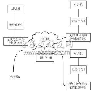
1 Introduction With the rapid development of radio station technology, more and more industries are beginning to use radio. The data transmission rate goes from low speed to high speed, and the transmitted signal develops from simple code to remote control telemetry data, digitized voice, dynamic image and so on. Because of its high stability and high reliability, the radio station is suitable for all kinds of wireless data acquisition and monitoring control systems, especially in the monitoring of oil and gas pipeline networks, urban air defense alarm control, railway signal monitoring, and power load monitoring , Urban street lamp monitoring, railway water supply centralized control, GPS positioning system, earthquake forecasting, sewage treatment, environmental monitoring and other industrial automation systems. 2. System Overview This article combines embedded technology with radio station communication technology to develop a new type of embedded network controller. The circuit board in the controller is based on the ARM9 embedded microprocessor, and provides multiple interfaces to the outside, including 3 serial ports, a small system bus interface, and very rich common embedded system interfaces, such as SPI x 1, I2C x 1. I2S x 1, AD x 2, PWM x 1, USB Host, USB Slave interface, etc. With these interfaces, we can expand the functions of the embedded network controller according to the needs. In this system, we mainly use 3 serial ports and Ethernet ports. The main principle of the radio station network controller design is: the radio station receives the voice signal sent by the interphone and outputs it to the network controller terminal through the audio cable. The voice codec chip in the controller is responsible for converting the analog voice signal into a digital signal. The software in the controller is responsible for compressing the audio data. The compressed voice data packet is sent to the server through the Internet. The server software forwards the data packet according to certain rules. To other network controller terminals. The controller that receives the voice compression code stream is responsible for decoding and D / A conversion. The voice signal is input to the radio station through the audio cable. Finally, the radio station sends the voice signal to the intercom through the internal transmission module. This process realizes the transmission of voice data across the Internet, and the user sends control instructions to the controller terminal through a PC or other network equipment. The software in the terminal is responsible for interpreting the instructions and transmitting the instructions to the radio through the serial port. The radio station then issues instructions to each controlled device, thus achieving remote control of the radio station and related equipment. 3. Hardware design Based on the analysis of the working principle of the network controller of the radio station, we made an overall design of the sub-modules and tasks of the system. The entire system can be divided into two relatively independent parts to complete: radio station network controller terminal and server software. Controller 1 sends the encoded g72x code stream to the server. The server forwards the data to controller 2, controller 3, controller 4 ... controller n according to the routing table information. TCP or UDP is used between the controller and the server protocol. The schematic diagram of the radio station network controller structure is shown in Figure 1. Figure 1 Structure diagram of the radio station network controller In addition to the selection of the core board, the hardware design is mainly the design of external circuits. We chose the SBC-2410 core board with better cost performance. The design of the peripheral circuit mainly includes an audio signal acquisition module, a network data transceiver module, a serial port control circuit, etc. [3], where the audio signal acquisition circuit we chose is the uda1341 voice codec chip, and the network controller chip we use the cs8900 chip. 3.1 Introduction to Embedded Core Board SBC-2410 has excellent characteristics such as high performance, low power consumption, rich interfaces and small size, and has been applied in multiple designs. Based on the idea of ​​reusability, the entire platform carries ARM's most streamlined system, passing useful signal lines through two Row pin out. The specific application of the radio station network controller terminal is designed according to actual needs, and is connected to the core board through two rows of sockets [4]. 3.2 Voice chip interface circuit Because the built-in IIS bus interface of S3C2410 can be used with multimedia codec chips provided by other manufacturers, the design of the internal voice module of the radio network controller terminal is based on the IIS (Integrate InteRFace of Sound) interface. Provide the IIS interface to read the data on the IIS bus, and also provide DMA (Direct Memory Access) transmission mode for FIFO (First Input First Output) data, which can simultaneously transmit and receive data. The IIS interface has three working modes, namely normal transmission mode, DMA mode and transmission / reception mode. In the design of this article, we have selected transmission / reception mode. In this mode, the IIS bus can simultaneously receive and send audio data. Solar Power System Accessories Solar Power System Accessories,Solar System Accessories,Solar Installation Kit,Solar Battery Kit SUZHOU DEVELPOWER ENERGY EQUIPMENT CO.,LTD , https://www.fisoph-power.com