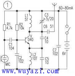
The circuit is a 1.5km single-tube FM transmitter circuit. The transmitting transistor adopts D40, D50, 2N3866, etc., and the working current is 60-80mA. However, the above triodes are difficult to purchase, and the price is higher, and there are more fakes. The author chooses other triode experiments, the relatively easy to buy triode C2053 and c1970 is quite good, the actual line-of-sight communication distance is greater than 1.5km. I also changed the D40 tube to the ordinary transistor 8050, the working current is 60 ~ 80mA, but the emission distance is less than 1.5km, if changed to 9018, the working current is smaller, the emission distance is also shorter. In addition to the transmitting transistor, the parameters of the coil L1 and the capacitor C3 are more important in the circuit. If not selected properly, the vibration or the operating frequency exceeds the range of 88 to 108 MHz. Among them, L1 and L2 can be used for ∮3.51mm enameled wire on a round bar of about 3.5mm, and a single layer is flatly wound 5åŒ and 10åŒ, and C3 is made of 5~20pF porcelain or polyester adjustable capacitor. In actual production, capacitor C5 can be omitted, and L2 can be replaced with a common inductor of 10 to 100 mH. If the emission distance is only tens of meters, then the battery voltage can be selected from 1.5V to 3V, and the D40 tube can be replaced with the inexpensive 9018, etc., and the power consumption will be less. The single-tube transmitter described in the figure has a simple circuit and output power. Large, easy to make, but it is not convenient to connect the high-frequency cable to send the RF signal to the outdoor transmitting antenna. Generally, the 0.7-0.9m rod antenna is directly connected to the C5 for transmission. Due to the Doppler effect, people are When moving near the antenna, the frequency drift phenomenon is very serious, causing the receiver sound that is normally sounded to be distorted or silent. If the transmitter is used as a wireless microphone, it is conceivable how severe the frequency drift is when the antenna is pinched. The circuit uses a three-point capacitor oscillator. When the antenna parameters are slightly changed, the running frequency phenomenon will occur. Furthermore, since it is a single-tube self-oscillating oscillation, the operating current is large. When the operation is several seconds to several minutes, the temperature of the triode The rise causes a change in the interelectrode capacitance, which also causes a change in the oscillation frequency (generally, the oscillation frequency is lowered), and sometimes the frequency drift is as high as 0.2 to 1 MHz. When used as an FM radio or remote remote alarm, the work reliability is poor, but the components are few, the cost is low, and the debugging is easy. It is suitable for junior enthusiasts to conduct experiments.
This type PLC Splitter devided from Material.Because this ABS BOX PLC Splitter material is ABS BOX,so we call it ABS BOX PLC Splitter.
We have including 1:4,1:8,1:16,1:32,1:64 this 5 models splitter in the group.The main function of this 5 models are the same ,the only difference just for the fiber cable numbers.It is optional for customers.Customers can choose the one the are needed in their network applications.
Warmly welcome customers all over the world to contact us for more products details.
Abs Box Plc,Abs Box type Plc Splitter,Plc Splitter,Passive Optical Network, Optical Splitter Shenzhen GL-COM Technology CO.,LTD. , https://www.szglcom.com