Fork Type Connecting Terminals Fork Type Connecting Terminals,Terminals,Connecting Terminals Taixing Longyi Terminals Co.,Ltd. , https://www.longyiterminals.com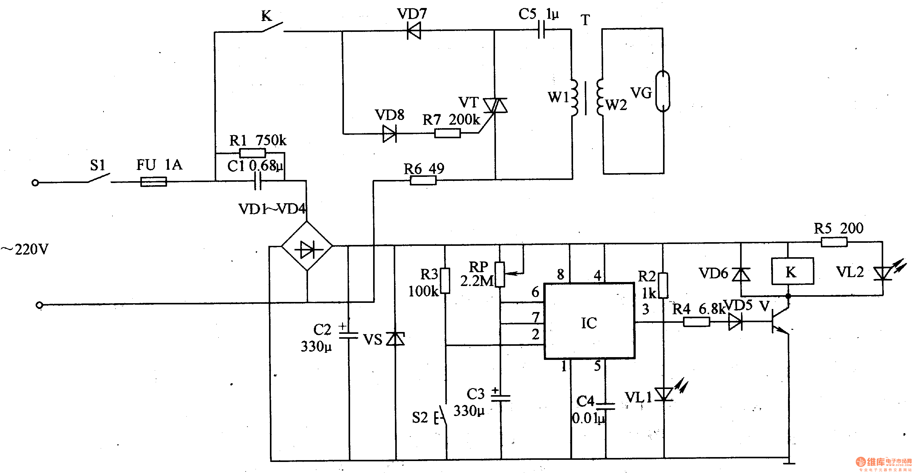
The power circuit is composed of a power switch S1, a fuse FU, resistors Rl, R2, capacitors Cl, C2, rectifier diodes VDl-VD4 and a Zener diode VS.
The timing control circuit is composed of resistors R3-R5, capacitors C3, C4, diodes VD5, VD6, transistor V, time base integrated circuit IC, timing button S2, relay K and light emitting diode VL2.
The ozone generator circuit is composed of normally open contacts of K, resistors R6, R7, capacitor C5, thyristor VT, step-up transformer T and ozone tube VG.
Turn on the power switch Sl, the AC 220V voltage is stepped down by Cl, VDl-VD4 rectification, C2 filtering and VS voltage regulation to generate +l2V voltage, one way directly to the timing control circuit; the other way is to reduce the VLl point after R2 current limiting step-down bright.
When disinfecting, press the button S2 to make the 3 pin of the IC output high level, VD5 and V are turned on, VUA is bright, K is energized, and the normally open contact of K is turned on, so that the ozone generator circuit is energized. The VT is intermittently turned on, causing the LC series resonant circuit (composed of the windings W1 of VT and C5, T) to oscillate, generating a pulsed high voltage on the winding W2 of the T, and generating ozone by discharging the ozone tube VG.
While the IC 3 pin outputs a high level, C is quickly discharged by the 7-pin internal circuit of LC, and then slowly charged by RP. When the voltage of C3 is charged to 8V or more, the circuit inside the IC is flipped, and the 3 feet are high. The level changes to low level, VD5 and V are cut off, K is released, the ozone generator circuit is powered off and stops working, and VL2 is extinguished.
Adjust the resistance of the RP to change the length of the timing.
Component selection
Rl-R5 and R7 select 1/4W metal membrane resistor or carbon membrane resistor for use; R6 selects 8-1OW cement resistor for use.
The RP uses a small organic solid potentiometer or a variable resistor.
C1 and C5 select CBB capacitors with a withstand voltage greater than 450V; C2 and C3 select aluminum electrolytic capacitors with a withstand voltage of 16V; C4 selects polyester capacitors or monolithic capacitors.
VDl-VD4 and VD6-VD8 select 1N4007 type silicon rectifier diode for use; VD5 selects type 1N4148 type silicon switch diode for use.
VLl and VL2 select φ5mm LEDs.
V selects S8050 type silicon NPN transistor.
VT selects TLC336A type bidirectional crystal tube.
The IC selects the NE555 type time base integrated circuit.
T is made of a ferrite core and a high-strength enameled wire: the winding W1 is wound with a φ1.2 mm enamelled wire 30 åŒ, and the winding WZ is wound with a φ0.09 mm enamel wire 2500 åŒ (the finished universal sealed step-up transformer can also be used).
The VG uses a Z-10 ozone generator.
K selects HG4099 type l2V DC relay.