First, AUTOSAR background introduction This article refers to the address: http:// AUTOSAR is the abbreviation of English AUTOMative Open Systems ARchitecture, which means the automotive open system architecture. It defines a set of software architecture development methods for supporting distributed, function-driven automotive electronic software development and electronic control units. Different car platforms improve software reuse and reduce development costs. AUTOSAR is a global alliance of automotive software development established by automotive OEMs and its first-line suppliers. It was formally established in the summer of 2003 and launched its main work in 2004 with the aim of controlling the complexity and diversity of automotive software. AUTOSAR consists of 9 core members: BMW Groups, BOSCH, Continental, DAIMLER, Ford, GM, PSA Peugeot Citron, TOYOTA (Toyota), VOLKSWAGEN AG (Volkswagen). At present, its members have more than 150. Domestic OEMs have already joined FAW and SAIC. Hengrun Technology has become the third company in China to join the organization after FAW and SAIC. Since the introduction of AUTOSAR, from the semiconductor industry, tools and software manufacturers, component suppliers to automakers themselves, the value system in the entire automotive field has been actively promoted by this standard. AUTOSAR development members released version 2.1 in 2007, which brought the development of AUTOSAR to a stable stage. Subsequently, the practicality of AUTOSAR was tested through several different development projects. Now AUTOSAR is ready to enter the product ECU. The BMW Group has applied AUTOSAR-compliant ECUs (Electronic Control Units) to the new BMW 7 Series production models. It is expected that all core members of AUTOSAR will launch related products in 2010. In the commercial world, tools and software vendors that support the AUTOSAR standard have introduced tools and software that provide requirements management, system description, software component algorithm model validation, software component algorithm modeling, software component code generation, RTE generation, Services such as ECU configuration and basic software and operating systems help OEMs implement a seamless AUTOSAR system software architecture development process. The AUTOSAR version is currently version 3.1 and is expected to be released in the fall of 2009. Since AUTOSAR advocates the principle of “cooperating on standards and competing in implementationâ€, its core idea is “unified standards, decentralized implementation, centralized configurationâ€, so the adoption of AUTOSAR will bring great benefits to OEMs, which will make them Software procurement and control have more flexibility and greater rights, because the standardization and openness of software systems will enable more software vendors to enter the automotive electronics industry, which will give them more choices, and software quality supervision will also A corresponding increase will help improve the quality of their products. However, it must also be seen that there are potential obstacles to implementing this standard across the industry, from the resistance of some OEMs and large first-tier auto suppliers, because they already have their own standards and architecture, and adopt AUTOSAR. Standards and their architecture can create risks such as replacement costs and loss of control. Nevertheless, the standardization of automotive electronic software development methods and software architecture is an unstoppable trend in the automotive industry, and there is currently no standard that goes further than the AUTOSAR standard. In view of this, domestic auto OEMs must be prepared to deal with AUTOSAR, which is a challenge for them. OEMs will play a leading role in the implementation of the AUTOSAR standard. How should OEMs make demands and use these software with standard features and interfaces from different vendors on their products? For this purpose, AUTOSAR has also developed a methodological and process standard, namely the AUTOSAR methodology. This article will focus on the interpretation of the AUTOSAR methodology and explain how OEMs should apply this standard to their product development and production processes. Second, AUTOSAR technology overview There are three main objectives of AUTOSAR, the first is to build a hardware-independent layered software architecture; the second is to provide a methodology for implementing applications, including the development of a seamless software architecture stacking process and the integration of application software into the ECU; The third is to develop various vehicle application interface specifications as application software integration standards, so that software components can be reused on different vehicle platforms. 1. AUTOSAR software architecture In order to achieve the goal of AUTOSAR, which is to achieve separation between the application and the base module, the automotive electronic software architecture is abstracted into several layers, as shown in Figure 1. In order to distinguish between software dependencies and hardware dependencies, the basic software is divided into four levels: the Services Layer, the ECU Abstraction Layer, the Microcontroller Abstraction Layer, and the RTE (Runtime Environment). In addition to the four layers, there is a Complex Driver in the AUTOSAR software architecture. Since the modules that operate on complex sensors and actuators involve strict timing issues, this part is not standardized in AUTOSAR. * The service layer provides system services including diagnostic protocols, storage management, ECU mode management, and operating system. In addition to the operating system, the software modules of the service layer are platform-independent. * The ECU abstraction layer abstracts the ECU structure (such as the connection between peripherals and ECUs). This layer is related to the ECU platform but not to the microcontroller. * The microcontroller abstraction layer includes microcontroller-related drivers (such as I/O drivers, ADC drivers, etc.). * The RTE layer is responsible for the communication between the AUTOSAR software components (ie the application layer) and the communication between the software components and the underlying software. The underlying software under the RTE layer is invisible to the application layer and must be accessed via RTE. It separates the software components from the dependencies on the underlying software and hardware platforms, enabling separation between the application and the underlying software. . 2, AUTOSAR methodology AUTOSAR defines a common technical approach to the development of automotive electronic software systems that conform to this standard. This approach is known as the AUTOSAR Methodology. As a planner and designer of vehicle system functions, automotive OEMs need to understand and master the development process provided by AUTOSAR in order to lead and promote the development process of AUTOSAR-compliant systems. The design and development process of the automotive electronic software system compatible with the AUTOSAR standard is shown in Figure 2. The main steps can be divided into two phases: The first phase is the system configuration phase, which is a system-level design decision. The first is to write a system configuration input file, which is an XML type file. The terminology of the application software is the software component in AOTUSAR, which determines the software components that need to be used (ie, what functions the system has) and the hardware resources (ECU), as well as the constraints of the entire system. AUTOSAR provides a series of templates (software component templates, ECU resource templates and system templates) and standard information exchange formats. Tool vendors can provide corresponding tool support to simplify system design. Finally, system designers only You need to populate or edit the appropriate template with a tool to export the system configuration input file. The system configuration input contains three parts. The first input is the software component description, which defines the interface content of each required software component, including data type, port, interface, etc. The second input is the ECU resource description, which defines each The ECU's resource requirements, such as processors, external devices, memory, sensors, and actuators; the third input is a system constraint description that defines the mapping between bus signals, topology, and software components. The next step in the system configuration phase is to generate the system configuration input file from the system configuration generator, which is also the XML configuration file. This is the final result of the system configuration phase. This document will contain all system information, including mapping software components to the relevant ECUs (this mapping needs to take into account the needs of the components, the connections of the components, the resource requirements and constraints, and sometimes the cost, etc.) And the communication matrix (the network structure of the vehicle, the timing and the content of the network data frame). The second phase is the configuration of the ECU. This phase of work needs to be done separately for each ECU in the system. The first is to use the first phase of the work results - the system configuration description file, to extract the system configuration description information related to each ECU, the extracted information includes the ECU communication matrix, topology, top-level functional combination (based on the generation of mapping All software components to the ECU will be placed in another XML file. The work of extracting information can be done with the help of tools. Then enter the actual work of the ECU configuration, this step is responsible for adding the necessary information for the specific application to the input object, such as task scheduling, necessary BSW module, BSW configuration information, and operational entities assigned to the task. The result of this step is placed in the ECU configuration profile, which contains all the information needed for a specific ECU. The final step is to generate the executable program of the specific ECU. This step will build the basic software of the ECU and integrate with the application software based on the AUTOSAR component according to the configuration information in the ECU configuration description file, and finally generate the executable code of the ECU. In addition, it should be noted that the design process of the AUTOSAR system uses the concept of the Virtual Functional Bus. The Virtual Functional Bus abstracts the communication between the AUTOSAR software components and the communication between the software components and the underlying software, using pre-defined standard interfaces. For the virtual function bus, there is no difference between the ECU internal communication and the external bus communication. This difference will not be reflected until the system layout and the specific functions of the ECU are finalized. The software components themselves are not concerned with this distinction, so we can develop software artifacts in a separate situation. In the system implementation process, the functions represented by the virtual function bus are finally embodied by the RTE generation. 3. Standardized application interface The premise that the AUTOSAR software components (ie, applications) communicate with each other and the communication between the software components and the base software through RTE is that the software components must have a standard AUTOSAR interface. At present, AUTOSAR version 3.1 has defined some standard interfaces for typical automotive electronics applications (power, body/comfort and chassis). AUTOSAR divides the systems in these fields into several modules according to functional logic. These modules can be regarded as a software component or a combination of multiple software components. The interfaces of these functional software components are clearly defined, and the interfaces defined are The content includes name, meaning, scope, data type, communication type, unit, and so on. Application software developers need to apply these interface definitions in the design and development of software components. Here, the interface of the software component managed by the wiper of the body/comfort system is defined as an example, as shown in Figure 3: Description: The WiperWasherManager has two interfaces, CmdWashing and StaWasher, and the WWManager in the figure is represented as an instance of the wiper management software component. The following information is defined for the CmdWashing interface: 1) The CmdWashing interface is provided by the WiperWasherManager component, and its data content is used by the Activation interface of the FrontWasher component. 2) CmdWashing contains a "Command" data element. 3) The data type of "Command" is "t_onoff". 4) "t_onoff" belongs to "RecordType", which describes general on/off information. Application software developers should be aware of the importance of application software design for the AUTOSAR runtime environment (RTE) interface, and early introduction of the AUTOSAR application layer interface into the actual project to achieve reusability of application software. Be prepared to optimize the entire software development process. Third, design application and implementation The design of the external vehicle light control system in the body/comfort area is still taken as an example, in this case only the implementation of the flicker control function of the turn signal is involved. In the system configuration phase, the first step is to collect system configuration inputs. First, collect the software components needed to implement this function. As shown in the right border of Figure 4, five software components are used in the system. The software component template provided by AUTOSAR is used to write the description file of each software component. Then the system is defined. The ECU resources used in the form form an ECU resource description file, as shown in the upper left border of Figure 4. There are three types of ECUs; the last is a system constraint description file that describes the network topology of the system. General OEMs need to provide software component descriptions and system constraint description files for use by component suppliers in the development of ECU systems. The generation of the above description files has special tools (such tools are collectively referred to as AUTOSAR description file editor) support, users only need to fill the tool with the specified content. The generation of software component description files requires obtaining information about interfaces, behaviors, direct hardware interfaces (I/O), running performance requirements (memory, power consumption, timing, etc.) of each software component; The file itself will contain 4 parts: * General characteristics: name, manufacturer, etc. * Communication properties: port, interface * Internal structure: sub-components, connection relationships * Required hardware resources: processing time, scheduling, memory size and type. Before the ECU resource description file is generated, it is necessary to obtain information about each sensor and sensor, hardware interface, hardware attributes (memory, processor, power consumption), connection and bandwidth, etc.; and the ECU description file itself will contain 7 Part: * General characteristics: name, manufacturer, etc. * Temperature (self, environment, cooling / heating) * Available signal processing methods * Available programming capabilities * Available hardware: microcontroller, architecture (eg multiprocessor); memory, interface (CAN, LIN, MOST, FlexRay), peripherals (sensor/actuator), connection (eg pin count). * Basic software modules for microcontrollers under RTE * Signal from pin to ECU abstraction layer Before the system constraint description file is generated, information about the entire system, such as bus system, protocol, communication matrix and attributes, function cluster, function deployment (distribution to the ECU), and the system constraint description file itself will contain three parts: * Network topology: bus (CAN, LIN, FlexRay), connected ECU, gateway, power supply * Communication (for each channel): communication matrix, gateway table * Mapping of software components After the system configuration input content described above is collected, the system configuration tool is used to export the system configuration file. This step determines which software component is running on which ECU, which generates the ECU configuration description; in addition, the communication matrix within the system is generated. As shown in Figure 5. After the above work is completed, the next step is to enter the ECU configuration phase. The configuration information of each ECU is extracted from the system configuration file, and its contents include the ECU communication matrix, topology, and top level function combination (ie, a combination of all software components to be mapped to the ECU). In addition, more specific configuration of the main parts of the basic software of AUTOSAR, such as RTE configuration, OS configuration, MCAL (microcontroller abstraction layer) configuration and communication protocol stack configuration, is required. The configuration of these software components currently has corresponding tool support to directly generate compilable header files for the integrated use of ECU system software. Before generating the ECU executable program, it is necessary to obtain the code of the relevant software component and the basic software, and then build the configuration header file of the above basic software, and finally generate the executable program of the ECU. As shown in Figure 6. In summary, the entire system design and development process can be represented by Figure 7. It should be noted here that the process may require multiple iterations to achieve optimality. Fourth, summary AUTOSAR is becoming a reality. Establishing such a standardized platform and implementing standardization will shorten the development time and test time of new products, thus helping enterprises achieve rapid market response. Many OEMs plan to use AUTOSAR in their next models. Many tools and software vendors in the market have introduced AUTOSAR-compliant tools or software support to provide a complete and seamless solution for the design and development of AUTOSAR systems. AUTOSAR is a huge leap in the process of standardization of automotive electronic software platforms, we need to learn and understand it. But it must also be noted that breaking a traditional software development platform across the entire car line requires a long process. We can build a hybrid platform of AUTOSAR and traditional software in the initial stage according to users' needs and goals. This is a feasible way to achieve smooth upgrade to AUTOSAR. In this process, the focus is not simply to use, the understanding of AUTOSAR's philosophy and ideas is the most important, because it will bring profound changes to the workflow and business model of automotive electronic software development. Customizable Adapters,Custom Power Adapters,Customizable Usb Adapters,Thunderbolt Otg Adapter Cable Dongguan Pinji Electronic Technology Limited , https://www.iquaxusb4cable.com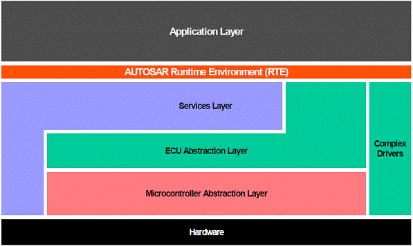
Figure 1: Level diagram of the AUTOSAR software architecture. 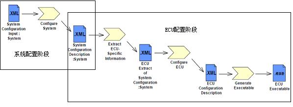
Figure 2: AUTOSAR system design and development process. 
Figure 3: Interface definition of software components. 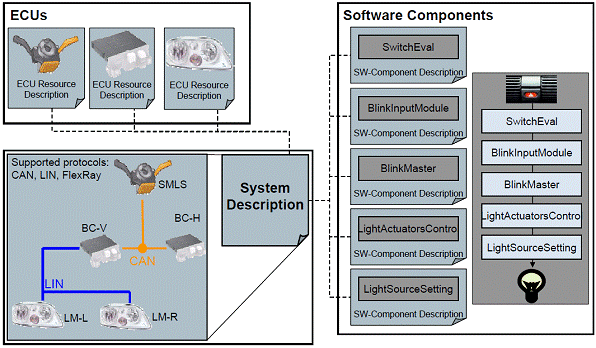
Figure 4: System configuration input. 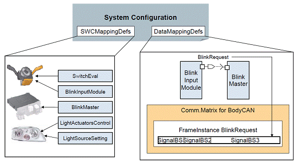
Figure 5: System configuration results. 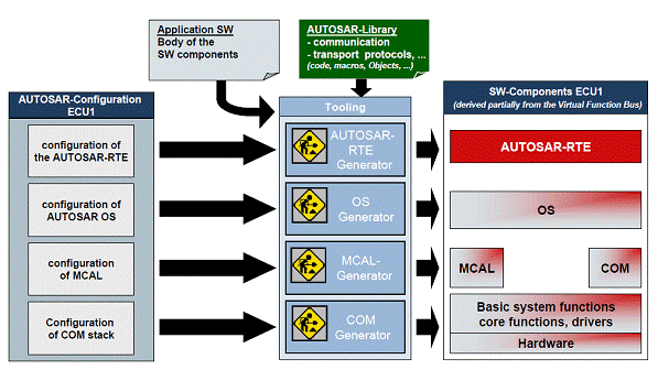
Figure 6: ECU configuration and executable program generation. 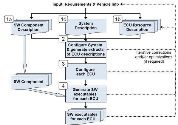
Figure 7: System design and development process.