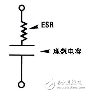
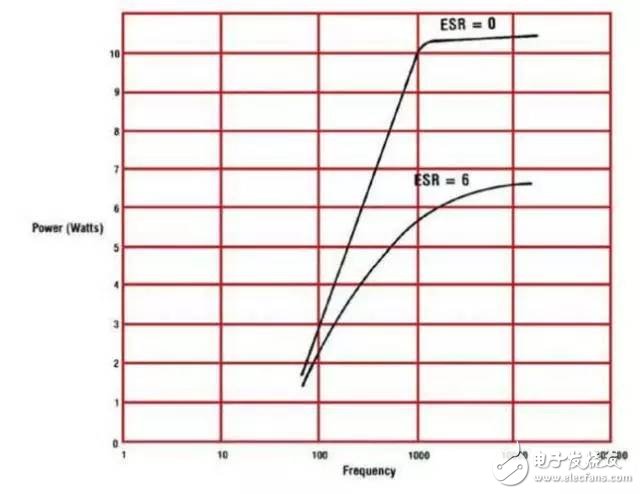
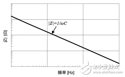
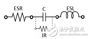
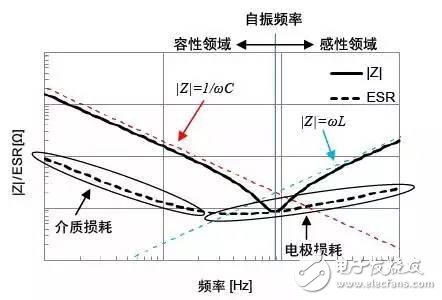
ESR is the abbreviation of the three words Equivalent Series Resistance, translated as "equivalent series resistance." In theory, a perfect capacitor does not produce any energy loss by itself, but in fact, because the material used to make the capacitor has resistance, the dielectric of the capacitor is depleted, and the capacitor becomes less than perfect for various reasons. This loss is external, and it appears as if a resistor is connected in series with the capacitor, so it has a name called "equivalent series resistance." If you think it is still too abstract, give you an intuitive explanation. ESR is present in any capacitor, and there is always an electrical resistance between the capacitor electrodes, such as metal pin resistance, electrode pad resistance, and connection resistance between them. The aluminum electrolytic capacitor also includes a resistor existing in a wet electrolyte solution, an electric resistance in an aluminum oxide (hydrated alumina) containing a high-level "water", and the like. The figure below shows the formation factors of the electrolytic capacitor ESR. Usually, in order to facilitate the analysis of the ESR of the capacitor, it is more simplified by the following diagram: Factors that cause ESR changes First, the resistance of the pin and capacitor electrode plates is negligible because they are very small. Two common factors that cause high ESR are: 1) poor electrical connection; 2) dryness of the electrolytic solution. For 1), both new and old electrolytic capacitors may appear; for 2) most of them occur on old electrolytic capacitors. The problem of poor electrical connection is mainly due to the fact that the pin leads connected to the inside of the capacitor are not aluminum metal materials, and aluminum has always been a non-weldable material. For the aluminum electrode plate material and the copper pin material, the electrical connection is mainly by the so-called "welding" and mechanical crimping. But both methods produce a higher ESR. As the electrolyte moisture evaporates, the ESR also increases. The figure below shows the output power as a function of output frequency for two 100 microfarad capacitors (ESR 0 and 6 ohms, respectively). At the low end (60 Hz), the difference between the two is small, but at the high frequency end (1 kHz), the difference is very large. The main factor in forming this difference is the relationship between the ESR and the capacitive reactance of the capacitor. Going further. If the angular frequency is assumed to be ω and the electrostatic capacity of the capacitor is C, the impedance Z of the capacitor (Fig. 1) under ideal conditions can be expressed by the formula (1). Figure Ideal Capacitor Z=1/jωC (1) It can be seen from the formula (1) that the impedance magnitude |Z| is as shown in the figure below, and the trend is inversely proportional to the frequency. Since there is no loss in the ideal capacitor, the equivalent series resistance (ESR) is zero. Figure Frequency characteristics of an ideal capacitor In practice, the frequency characteristic of |Z| is V-shaped (some capacitors may become U-shaped) as shown in the figure below, and ESR also shows the frequency characteristics corresponding to the loss value. Figure actual capacitor Figure |Z|/ESR frequency characteristics of the actual capacitor (example) The reason why |Z| and ESR become curves is as follows: Low frequency range: |Z| in the low frequency range is the same as the ideal capacitor, and both tend to be inversely proportional to the frequency. The ESR value also shows characteristics corresponding to the dielectric loss caused by the dielectric polarization delay. Near the resonance point: When the frequency increases, |Z| will be affected by the ESR caused by the parasitic inductance or the specific resistance of the electrode, and will deviate from the ideal capacitor (red dotted line), showing the minimum value. The frequency at which |Z| is the minimum value is called the natural frequency, and |Z|=ESR. If it is greater than the natural frequency, the component characteristics are converted from capacitors to inductors, and |Z| is increased. A range below the natural frequency is called a capacitive field, and vice versa is called an inductive field. In addition to the dielectric loss, ESR is also affected by the loss of the electrode itself against the stroke. High frequency range: The characteristic of |Z| in the high frequency range above the resonance point is determined by the parasitic inductance (L). The |Z| in the high frequency range can be approximated by the formula (2) and increases in proportion to the frequency. ESR gradually showed the effects of electrode skin effect and proximity effect. Importantly, the higher the frequency, the less the effects of parasitic components ESR or ESL can be ignored. With the increasing use of capacitors in the high frequency field, ESR and ESL, like electrostatic capacitance values, are important parameters for capacitor performance. Shenzhen Kate Technology Co., Ltd. , https://www.katevape.com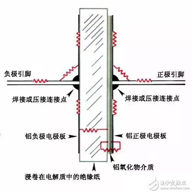
ESR is related to the leakage of electrolytic capacitors. Leakage is the parallel resistance between the capacitor plates. The ESR is only a series resistor, so the two are completely different, that is, the ESR is independent of leakage. Conversely, the leakage current can be reduced when the ESR is large enough.
The impact of ESR The emergence of ESR has led to the behavior of capacitors deviating from the original definition. For example, we believe that the voltage on the capacitor cannot be abrupt. When a current is suddenly applied to the capacitor, the capacitor will rise from 0 because it charges itself. But with ESR, the resistor itself produces a voltage drop, which causes a sudden change in the voltage across the capacitor. Undoubtedly, this will reduce the filtering effect of the capacitor, so many high-quality power supplies, such as low-ESR capacitors. Similarly, in the case of an oscillating circuit or the like, the ESR also causes a change in the function of the circuit, causing serious consequences such as circuit failure or even damage. So in most cases, low ESR capacitors tend to perform better than high ESR.
The relationship between ESR and frequency The following figure shows the DC blocking capacitor used in the audio output circuit (the red circle in the figure is the capacitor). 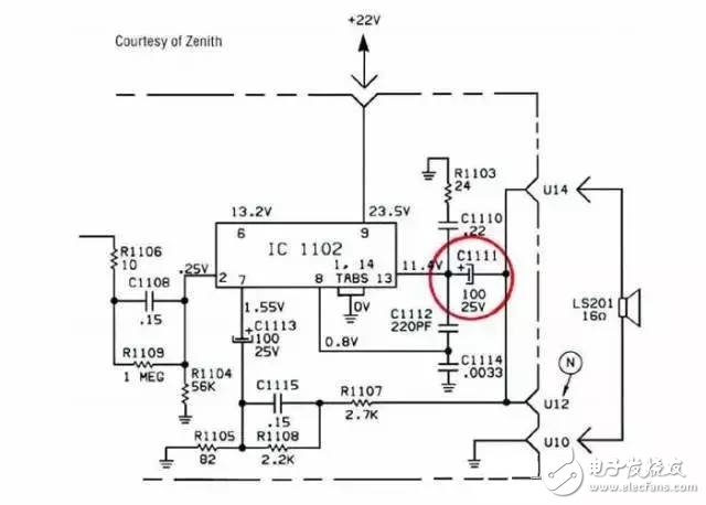
The relationship between ESR and power is prone to problems even when the capacitor is required to carry a large current even at a low operating frequency. For example, in some high current switching power supplies. For example, a 20,000 microfarad capacitor operating in a 60 Hz, 5A power supply, assuming its ESR is 0.5 ohms, then according to Ohm's law P = I × I × R, the capacitor will internally consume 12.5W of power. The heat generated will accelerate the drying of the electrolyte and cause the capacitor to fail. ESR also reduces the filtering effect. If there is a 0.5 ohm resistor in a 5V TTL supply circuit, a ripple voltage of up to 2V will be generated, which is equivalent to a ripple voltage of 40%. If the capacitor works in a high frequency, high current circuit, the situation will be more serious.
ESR also has "positive energy"
ESR is also useless, it will also be used to do useful things. For example, in a voltage regulator circuit, there is a certain ESR capacitor. When a load transient occurs, it will immediately generate fluctuations and trigger the feedback circuit action. This fast response is obtained at the expense of a certain transient performance. Quick adjustment capability, especially when the response speed of the power tube is slow, and the volume/capacity of the capacitor is strictly limited. This situation can be found in some three-terminal regulators or similar circuits that use mos tubes as adjustment tubes. At this time, too low ESR will reduce overall performance. ESR is an equivalent "series" resistor, meaning that connecting two capacitors in series will increase this value, while paralleling will reduce it. In fact, more ESR is needed, and low-ESR bulk capacitors are relatively expensive. Therefore, many switching power supplies adopt a parallel strategy that uses multiple ESRs with relatively high aluminum electrolysis to form a low ESR. Capacity capacitor. Sacrificing a certain amount of PCB space, in exchange for the reduction of device costs, is often cost-effective. Another concept similar to ESR is ESL, which is the equivalent series inductance. Early coiled capacitors often had very high ESL, and the larger the capacity, the larger the ESL. ESL is often part of the ESR, and ESL can also cause some circuit failures, such as series resonance. However, the relative capacity, ESL ratio is too small, the probability of problems is small, coupled with the progress of the capacitor manufacturing process, has now gradually ignored the ESL, and the ESR as a major reference factor in addition to capacity. By the way, the capacitor also has a quality coefficient Q similar to that of the inductor. This coefficient is inversely proportional to the ESR and is frequency dependent and less used.
Why are manufacturers not willing to label ESR?
Taking an electrolytic capacitor as an example, the resistance of the electrolyte is the main part of the equivalent series resistance (ESR) of the aluminum electrolytic capacitor. The main reason why most aluminum electrolytic capacitor manufacturers do not give ESR data is that the ESR of aluminum electrolytic capacitors is too large compared to capacitors of other media. For example, a typical aluminum electrolytic capacitor of 1μF/16V has an ESR of about 20Ω; a 100μF aluminum electrolytic capacitor has an ESR of 1.5 to 2Ω. Imagine that such data written in the data sheet will definitely affect the applicator's confidence in the application of aluminum electrolytic capacitors. Therefore, in some cases, the application of aluminum electrolytic capacitors is a helpless choice. Will affect the application of aluminum electrolytic capacitors. For aluminum electrolytic capacitors for general applications, most aluminum electrolytic capacitor manufacturers do not give ESR data. This data is given for low-ESR aluminum electrolytic capacitors for switching power supplies or pin-type aluminum electrolytic capacitors with relatively large capacitance.
Other circuit faults caused by ESR are often difficult to detect, and the effects of ESR are easily overlooked during the design process. In a simple way, if you can't select the specific parameters of the capacitor during the simulation, you can try to artificially connect a small resistor in the capacitor to simulate the effect of ESR. Generally, the ESR of the tantalum capacitor is usually below 100 milliohms. Aluminum electrolytic capacitors are higher than this value, and the ESR of some types of capacitors can be as high as several ohms. The relationship between the ESR value and the ripple voltage can be expressed by the formula V=R(ESR)×I. In this formula, V represents the ripple voltage, and R represents the ESR of the capacitor, and I represents the current. It can be seen that when the current is increased, the ripple voltage is multiplied even when the ESR remains unchanged.